Electromagnet for controlling hydraulic valve

A technology of electromagnets and hydraulic valves, applied in the field of electromagnets, can solve problems such as impermissibility, high hysteresis, and increased manufacturing costs

Inactive Publication Date: 2006-08-30
SCHAEFFLER TECH AG & CO KG
View PDF1 Cites 5 Cited by
  • Summary
  • Abstract
  • Description
  • Claims
  • Application Information

AI Technical Summary

Problems solved by technology

This misalignment of the axis may cause the radial air gap size between the armature and the armature guide and / or between the push rod and the axial hole to be different and cause the armature or push rod to abut against the armature guide at a certain position when the solenoid is energized Or on the axial hole, so that a friction force acts on the armature against its direction of motion, which may lead to impermissibly high hysteresis
In addition, the eccentric pressure equalization channels provided on the armature and the lower pole piece have also proven to be very complex, since these usually have to be drilled and the eccentric arrangement of these bores significantly increases the manufacturing effort

Method used


Image

  • Electromagnet for controlling hydraulic valve
  • Electromagnet for controlling hydraulic valve
  • Electromagnet for controlling hydraulic valve

Examples


Embodiment Construction

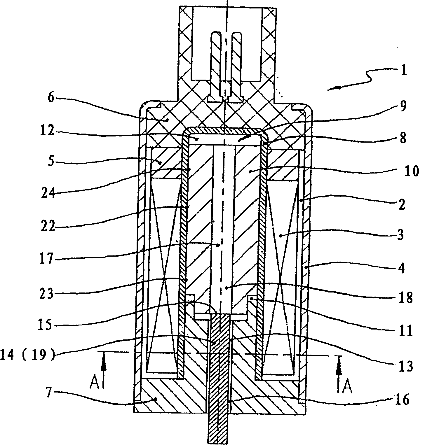
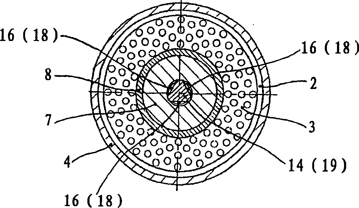
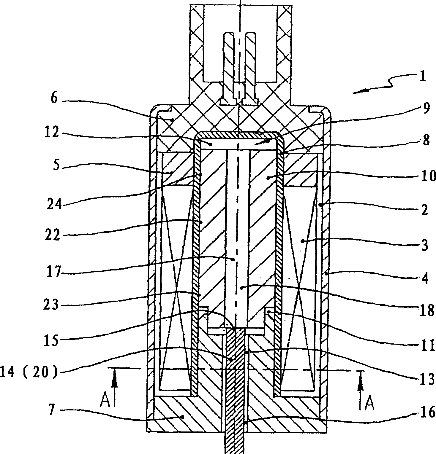
[0018] Depend on figure 1 , 3 and 5 clearly show the electromagnet 1 which constitutes a proportional magnet, which is especially suitable for controlling a hydraulic valve, not shown, which is used to control the device for changing the control time of the gas exchange valve of the internal combustion engine. It can be clearly seen that this electromagnet 1 has a hollow-cylindrical coil body 2 which carries the coil winding 3 and is surrounded on the outer circumference by a magnet housing 4 which is surrounded at the ends by an upper pole piece 5 and a lower pole piece. The shoe 7 defines that an electrical connection part 6 bears against the upper pole shoe, and the lower pole shoe protrudes into the hollow cylinder of the coil body 2 . Furthermore, a non-magnetizable metal tube 8 is arranged in the hollow cylinder of the coil body 2 , the cavity of which is designed as the armature chamber 9 of the axially displaceable cylindrical armature 10 . The armature 10 divides the...


PUM


Abstract

The present invention relates to an electromagnet (1) which includes a hollow, cylindrical coil body (2) that has at least one winding coil (3) and surrounded by a magnet housing (4). The coil body (2) is defined by an upper pole shoe (5) and a lower pole shoe (7). A nonmagnetic metal tube (8) is disposed in the hollow cylinder of the coil body and has an internal cavity which defines an armature chamber (9) for a cylindrical magnet armature (10). The magnet armature (10) divides the armature chamber (9) into a first chamber (11) and a second chamber (12) that interconnected by pressure equalizing channel in the magnet armature (10). The magnet armature (10) is connected to a control piston in a valve housing of a hydraulic valve through a tappet push rod (14) guided through an axial bore (13) formed to a lower pole shoe (7). The inner space of the valve housing is connected to the first chamber (11) of the armature chamber (9) by another pressure equalizing channel on the lower pole shoe (7). According to the present invention, the tappet push rod (14) is designed separating from the magnet armature (10) and is an independent profiles rod, and its section shape is different from the axial bore (13) and its section area is smaller than that of the axial bore (13). Furthermore, the magnet armature (10) has a central vertical bore (17) with diameter smaller than the maximum profiles width of the tappet push rod (14) and larger than the minimum profiles width of the tappet push rod.

Description

technical field [0001] The invention relates to an electromagnet, which particularly advantageously enables the realization of a proportional magnet for controlling a hydraulic valve, which is arranged within a hydraulic system of a device for varying the control time of a gas exchange valve of an internal combustion engine. Background technique [0002] An electromagnet of this type for controlling a hydraulic valve is known from DE 195 04 185 A1, which has a coil body carrying at least one coil winding and is surrounded on the outer circumference by a magnet housing. The coil body is bounded at the end by the upper pole piece composed of the ring-shaped pole plate and the inserted pole tube and the lower pole piece composed of the pole plate and the formed pole core. The electrical connector is against the upper pole piece, and The lower pole piece protrudes into the hollow cylinder of the coil body. The hollow cylinder of the coil body is simultaneously covered by a non-...

Claims


Application Information

Patent Timeline
Patent Type & Authority Patents(China)
IPC IPC(8): F15B13/044F16K31/06H01F7/08H01F7/16
CPCH01F7/081H01F7/1607F01L2001/34426F01L2820/031F01L1/3442F16K31/06
Inventor 延斯·谢弗
Owner SCHAEFFLER TECH AG & CO KG
Why Eureka
Try Eureka