Suspension spring

A hanger and spring device technology, which is applied to electric vehicles, power collectors, collectors, etc., can solve problems such as uncertain spring characteristics, wear, and limit the movement margin of the hanger, and achieve the effect of small air resistance

Inactive Publication Date: 2006-09-06
BOMBARDIER TRANSPORTATION GMBH
View PDF4 Cites 0 Cited by
  • Summary
  • Abstract
  • Description
  • Claims
  • Application Information

AI Technical Summary

Problems solved by technology

Depending on the design and orientation of the spring device, the elastic movement part may also be in the direction of travel, so that the suspension frame moves horizontally due to the travel relative to the air flow; this limits the movement allowance of the suspension frame
For high driving speeds, the known spring arrangement partly exhibits an indeterminate spring characteristic and severe wear in the hanger

Method used


Image

  • Suspension spring
  • Suspension spring
  • Suspension spring

Examples


Embodiment Construction

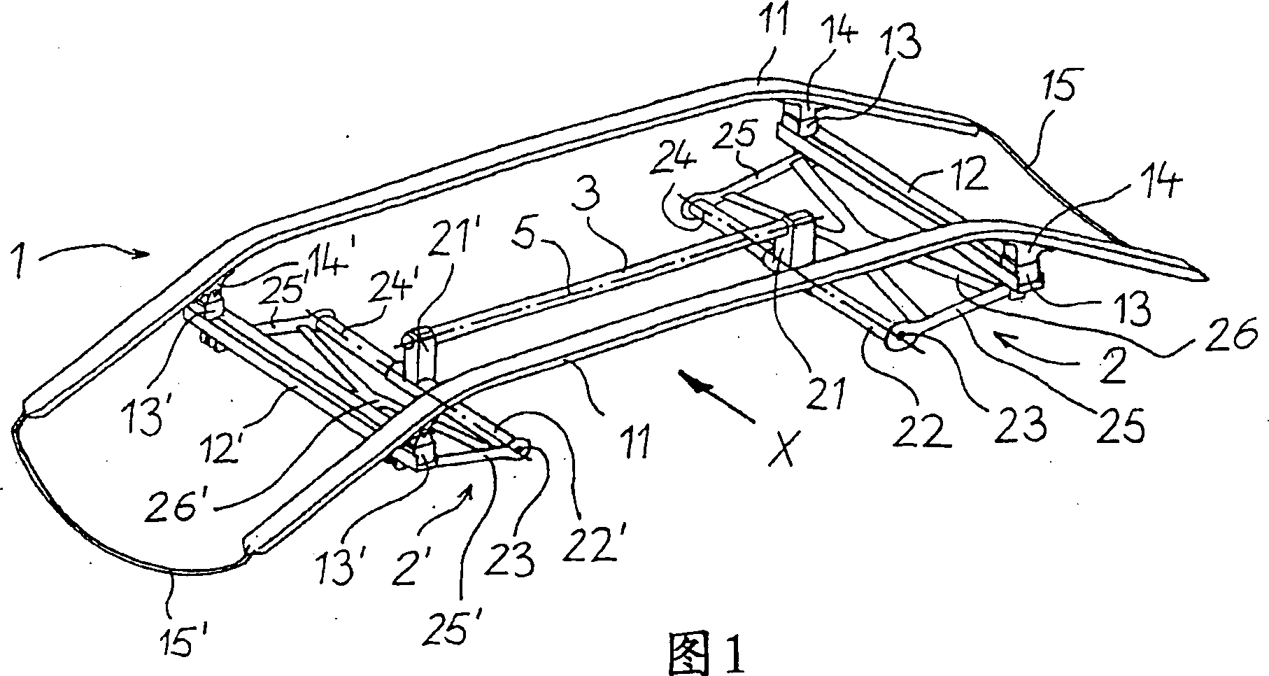
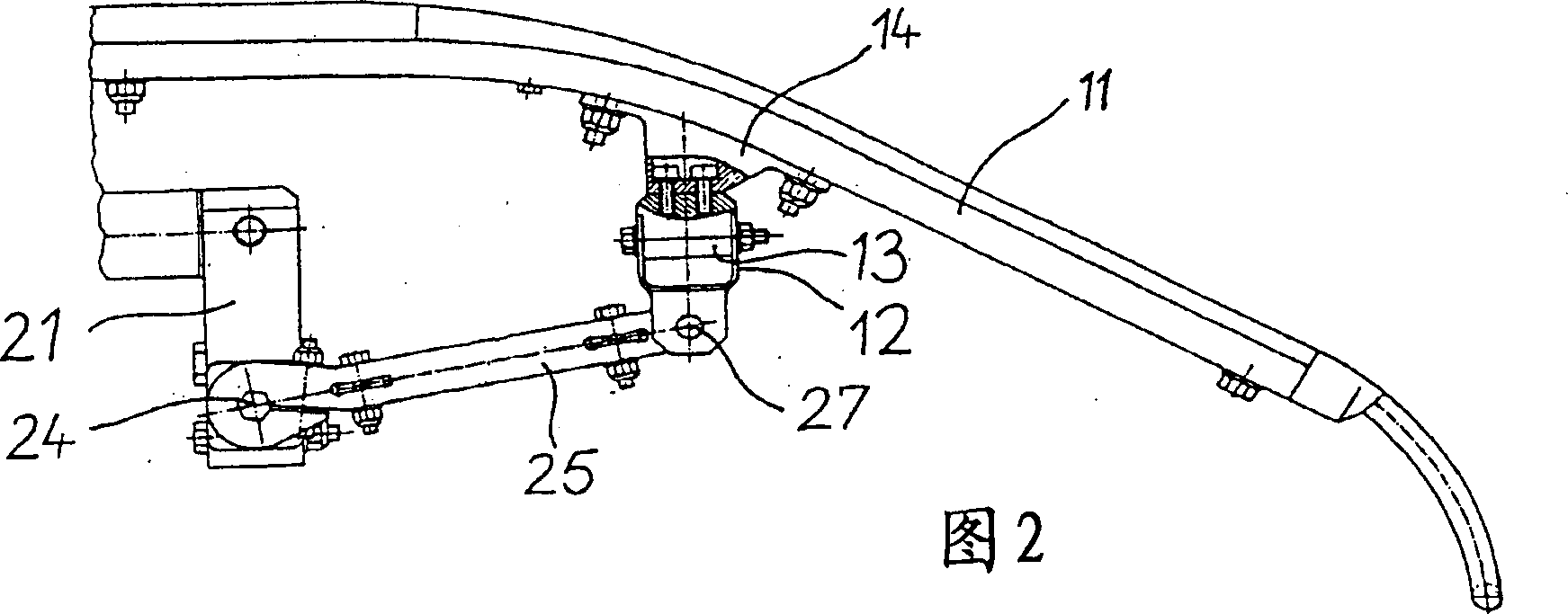
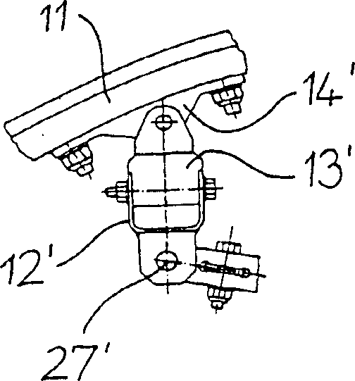
[0028] According to FIG. 1, a hanger for a current collector of an electric vehicle, such as a high-speed rail vehicle, has a frame 1 which is supported on a top shaft 3 via two spring devices 2, 2'. The frame 1 comprises two parallel sliding plates 11 extending perpendicularly to the traveling direction X for collecting electricity from trolley wires not shown in the figure and two supporting members 12, 12' extending parallelly along the traveling direction X. The supports 12, 12' are designed as upwardly open U-profiles, wherein a clamping section 13, 13' is inserted for each sliding plate 11, which can be inserted along the U-profile and screwed in the desired position. Mounts 14, 14' are attached to the underside of the slide 11, which are connected to the clamping sections 13, 13'. On each side of the vehicle, the ends of the sliding plate 11 are connected by sliding upper bows 15 , 15 ′, whereby the sliding wires sliding sideways can be redirected onto the carbon blocks...


PUM


Abstract

The invention relates to a bow suspension for a current collector of electrically driven vehicles, in particular rail vehicles. Said bow suspension comprises a frame (1) which has a pantograph contact strip (11) that is supported on an apex shaft (3) by a spring arrangement (2, 2'), said apex shaft (3) being rotatably mounted in an apex tube for connection to a chassis of the current collector. The spring arrangement (2, 2') of said bow suspension has a torsion spring (23, 23') and exhibits a defined rigidity that is independent of the airstream, even at high-speed operation, and a vertical spring displacement which is predetermined by the network operator.

Description

technical field [0001] The invention relates to a hanger for a current collector. Background technique [0002] DE 36 11 940 A1 discloses a single-arm current collector for electric vehicles comprising a double pantograph with sliding plate. The sliding plate section of the double pantograph forms a frame with two sliding upper bows (Auflaufbügel) rigidly fixed at both ends, which is mounted on the jacking tube of the upper pantograph wall rod by means of double rubber-spring elements or leaf springs in such a way Upper cushioning, ie such that the plane in which the elastic movement takes place is perpendicular to the direction of travel. Such relatively large sliding bows cause unfavorable aerodynamic forces and torques in the spring plane at high speeds due to their large area and large distance from the spring pivot point. [0003] A current collector for an electric vehicle is known from DE 42 19 112 A1, which has a frame-shaped hanger with slide plates, which is fast...

Claims


Application Information

Patent Timeline
Patent Type & Authority Patents(China)
IPC IPC(8): B60L5/22
CPCB60L5/22B60L2200/26
Inventor 斯文・巴特尔斯卡尔・耶格
Owner BOMBARDIER TRANSPORTATION GMBH
Why Eureka
Try Eureka