Air foil configuration for wind turbine

A wind turbine and airfoil technology, applied in the field of airfoil structure, can solve the problem of non-optimization of the composite airfoil and achieve good performance

Inactive Publication Date: 2006-10-18
GENERAL ELECTRIC CO
View PDF0 Cites 0 Cited by
  • Summary
  • Abstract
  • Description
  • Claims
  • Application Information

AI Technical Summary

Problems solved by technology

Certain aspects of the design are not yet clearly understood, and prior art composite airfoil designs are by no means optimal

Method used


Image

  • Air foil configuration for wind turbine
  • Air foil configuration for wind turbine
  • Air foil configuration for wind turbine

Examples


Embodiment Construction

[0106] As above, using the formula:

[0107] (Formula 16)

[0108] to derive the maximum aerodynamic criterion for the optimal airfoil.

[0109] where Equation 16 can be used to calculate the rotor size for a 15% load reduction. For example, taking Tackes' TW1.5s turbine with a 70.5m rotor and a 1500KW rated power, it can be determined that the load will be reduced by 15% when the blade stiffness is halved. The rotor can then be scaled up according to the following formulas, derived from Equation 16:

[0110] (M 额定 ) 较大的,可变的 =(M 额定 ) 基准,可变的 (R 较大的 / R 基准 ) 5 / 3 =.85(M 额定 ) 基准 (R 较大的 / R 基准 ) 5 / 3 =(M 额定 ) 基准 (Formula 17)

[0111] And, in order to find the diameter of the new rotor, we can get:

[0112] R 较大的 / R 基准 =(1 / .85) / 6=1.10 (Equation 18)

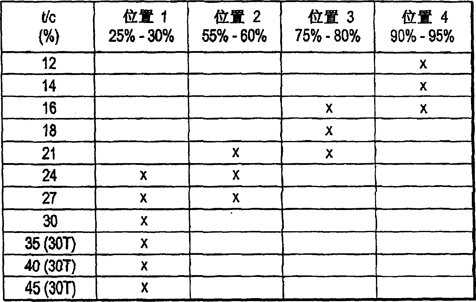
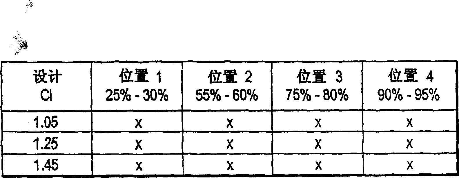
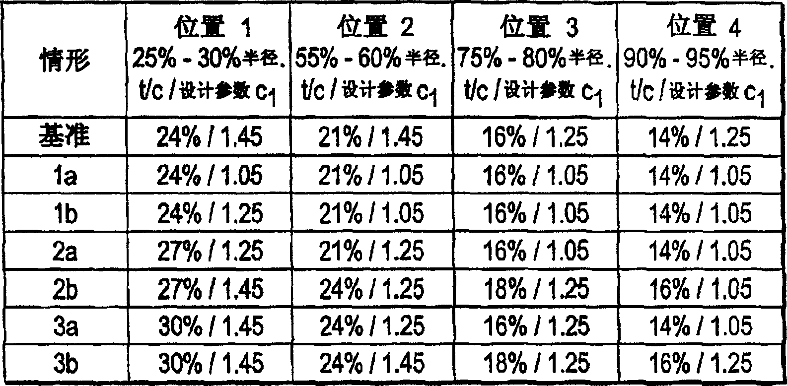
[0113] Once completed, the example Figure 1-13 Modifications to the design are made based on the graph information collected in identifying the structural features to modify the opti...


PUM


Abstract

The balance of aerodynamic optimization and structural optimization provides a wind turbine airfoil with significantly improved performance. The mathematical model yields a maximum aerodynamic criterion which, combined with structural analysis, refines the optimal aerodynamic design to a balanced, greatly optimized airfoil structure. This synthetic airfoil has a significant performance impact on GAEP. The airfoil is based on a theoretically optimized aerodynamic structure, which is modified as necessary to maximize structural integrity. A method for maximizing airfoil performance enables the design of the airfoil to achieve predetermined performance while achieving the desired structural integrity. The airfoil family offers significant improvements in operational and structural performance, including thickness/chord ratios ranging from 14% to 45%.

Description

technical field [0001] The present invention relates generally to wind turbines, and more particularly to a set of airfoil structures for optimizing the performance of wind turbines. Background technique [0002] Wind turbines are well known. The turbine blade or airfoil is one of the main factors in determining the efficiency of the system and therefore a key factor in optimizing performance. Typically, turbine rotor blade design is performed by first identifying a set of airfoils to be used; then determining the optimum span distribution of strength and twist in order to optimize the power coefficient at the spanwise position. The blades formed by this process are usually not optimal structures for special applications. Various efforts have been made over the years to optimize the blade structure, with varying results. [0003] As an example, Zood Energy Systems, Inc. (assignee of the present invention) has used a thinner airfoil structure than its European counterpart....

Claims


Application Information

Patent Timeline
Patent Type & Authority Patents(China)
IPC IPC(8): F03B3/12F03D1/06
CPCF03D1/0641F05B2240/301Y02E10/72Y10S416/02Y10S416/05
Inventor M·S·塞利格K·K·韦策尔
Owner GENERAL ELECTRIC CO
Why Eureka
Try Eureka