One division cam mechanism with cambered surface

A cam mechanism and cambered cam technology, which is applied to rotary printing presses, printing presses, labeling machines, etc., can solve the problems of limitation of output accuracy improvement, accumulation of structural errors, and difficulties in processing and manufacturing of plane cam indexing mechanisms. The effect of good rigidity, high precision and simple structure

Inactive Publication Date: 2007-01-03
XI AN JIAOTONG UNIV
View PDF6 Cites 0 Cited by
  • Summary
  • Abstract
  • Description
  • Claims
  • Application Information

AI Technical Summary

Problems solved by technology

[0005] At present, the single-division planar cam mechanism is widely used in hot stamping die-cutting machines. Due to the limitation of the planar cam, only the structure of multi-piece cam and multi-layer roller can be used. The error accumulation of this structure is serious, and the improvement of output accuracy is severely limited; With the development of the packaging and printing industry in the direction of high speed and high precision, the moment of inertia of the load caused by high-speed motion increases. Due to the design limitation of the one-division planar cam mechanism, the size of the mechanism can only be rapidly increased to meet the load requirements. The processing and manufacturing of the mechanism brings great difficulties

Method used


Image

  • One division cam mechanism with cambered surface
  • One division cam mechanism with cambered surface
  • One division cam mechanism with cambered surface

Examples


Embodiment Construction

[0019] Accompanying drawing is the specific embodiment of the present invention;

[0020] Below in conjunction with accompanying drawing, structural principle and working principle of the present invention are described in further detail:

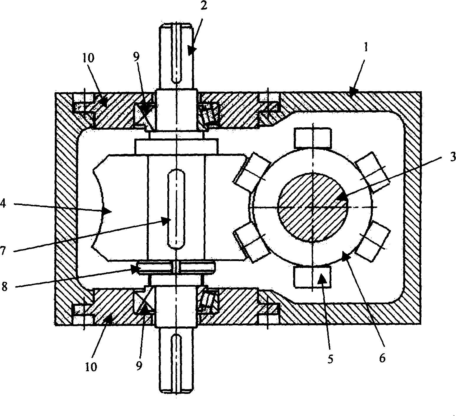
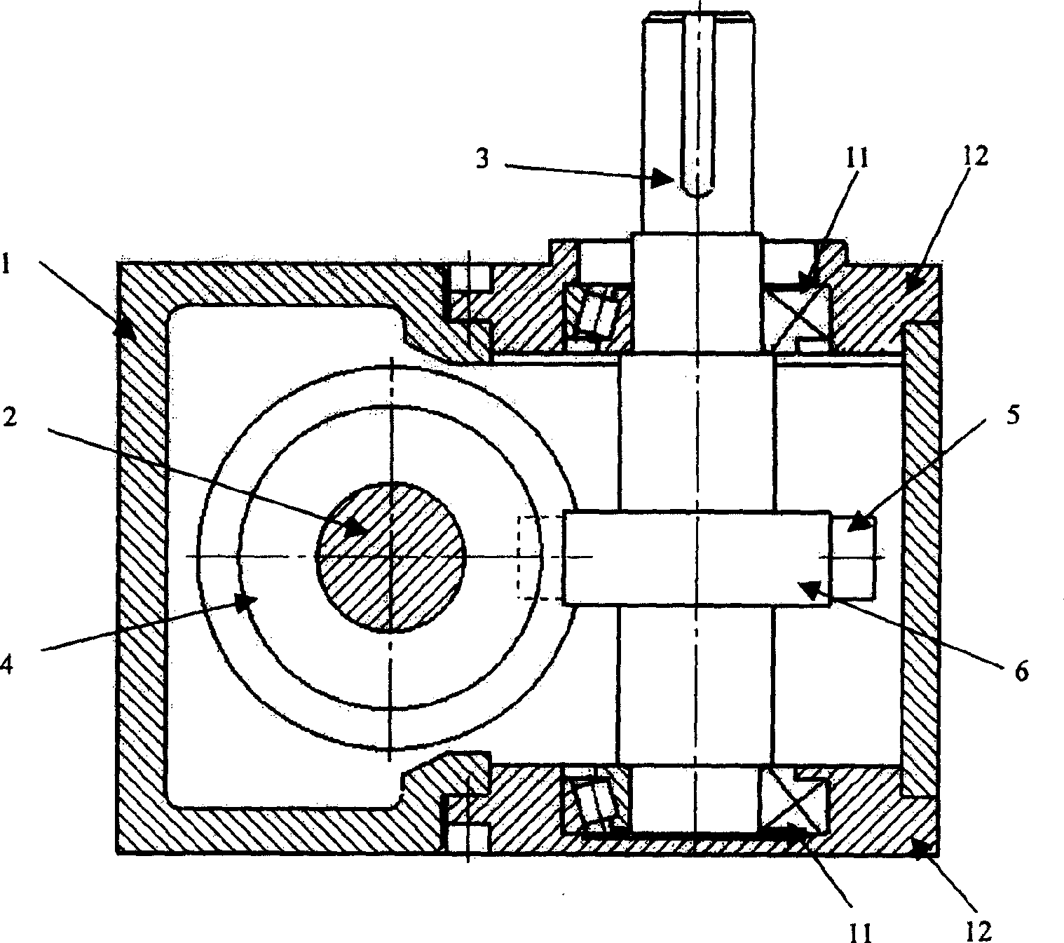
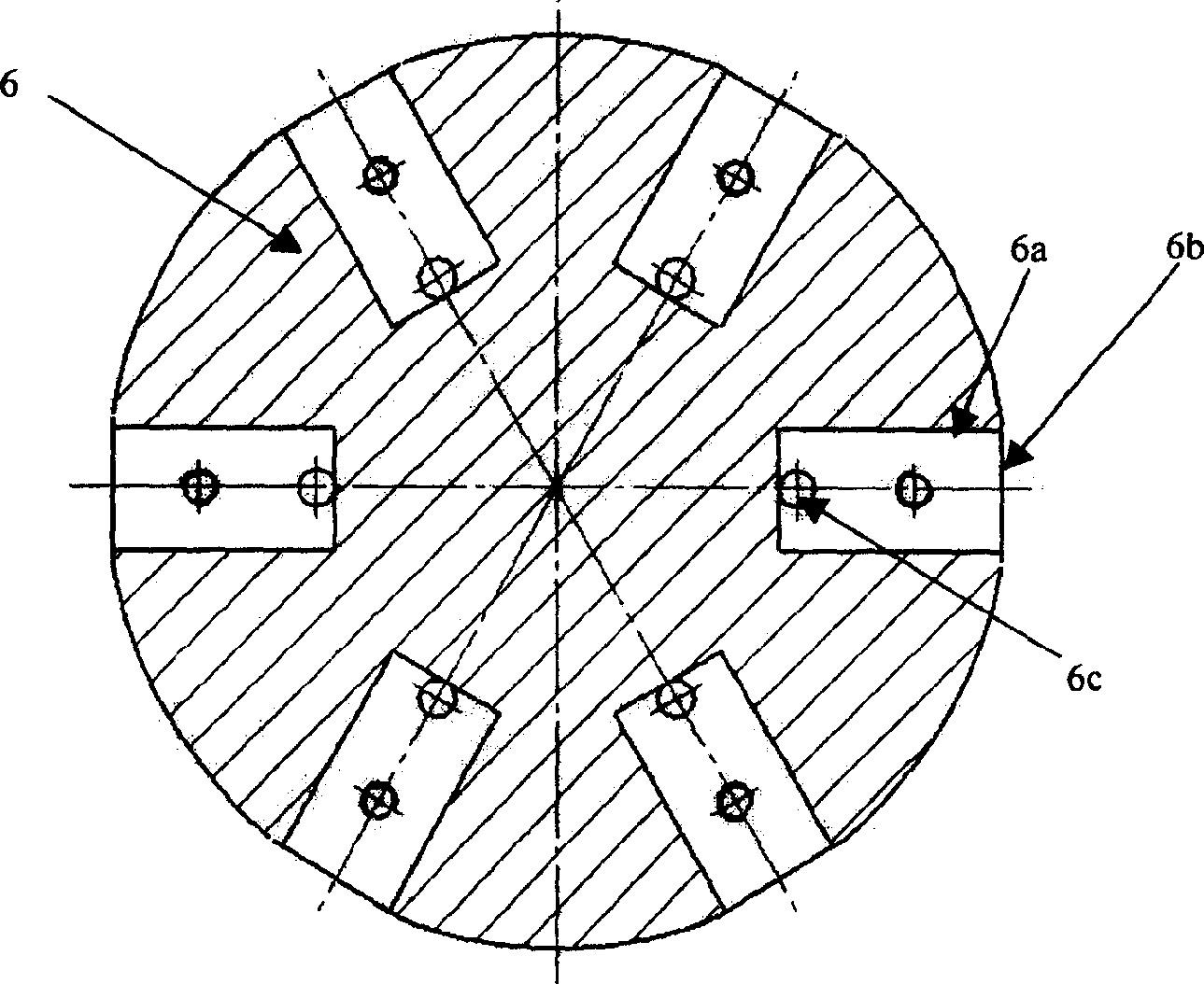
[0021] refer to figure 1 , figure 2 As shown, the present invention includes a base 1 with a rectangular box shape, on which an input shaft 2 and an output shaft 3 are installed, and input and output bearing end covers 10, 12 are respectively arranged on both sides of the base 1, and its characteristics The input shaft 2 has two input ends, the input shaft 2 is fixed with an arcuate cam 4 with six ridges 4a-4f, the arcuate cam 4 is connected to the input shaft 2 by a key 7, and one end of the arcuate cam 4 It is fixed with the shaft shoulder of the input shaft 2, and the other end is locked by the fastener 8. The output shaft 3 is fixed with a driven disc 6, and the driven disc 6 is radially and equally divided and installed to engage wi...


PUM


Abstract

This invention deals with a cam mechanism of one division cambered surface in the packaging and printing trade. Its basal body is installed with import shaft and output shaft, both sides of the body are set up the end caps of input and output bearings. The input shaft has two input ends and the fixed cambered cam with six convex ridges, the output shaft has a fixed side traveling pan on which are radially installed six rollers which mesh the cambered cam. The input shaft brings the cambered cam into the even movement, and the six convex ridges on the cambered cam will in turn touch the six rollers on the side traveling pan. The cambered cam drives the side traveling pan to rotate 360 degrees according to the predetermined moving rule. When the rollers touch the straightway convex ridges, the side traveling pan will keep still; when the cambered cam begins another circling, the one division movement of the output shaft can be realized. This invention is easily manufactured with high division precision and accurate positioning and close structure, and it also possesses the high rigidity and intensity, good bearing capacity, long operating life and high driving efficiency.

Description

technical field [0001] The invention belongs to the field of packaging and printing machinery, and in particular relates to a one-division cam mechanism for intermittent indexing. Background technique [0002] In recent years, with the development of the economy and the improvement of people's living standards, various new packaging products have emerged, including various packaging covers made of aluminum foil, PE coated paper (such as yogurt covers, instant noodle bowls, etc.) cover, civil aviation lunch box cover), various trademarks, bottle stickers, labels, etc. are made of aluminum foil and aluminized paper. These products often require the use of various new or even special-purpose die-cutting machines due to high precision requirements and special materials. Package web bronzing mold machine and so on. [0003] The bronzing die-cutting machine used in the packaging and printing industry is mainly composed of paper feeding, die-cutting, bronzing, chip removal, paper...

Claims


Application Information

Patent Timeline
Patent Type & Authority Patents(China)
IPC IPC(8): B65B61/00B65C11/02B41F17/00F16H29/20
Inventor 陈雪峰何正嘉訾艳阳张周锁高强安宁丽
Owner XI AN JIAOTONG UNIV
Why Eureka
Try Eureka