Lens barrel
A lens barrel and lens group technology, applied in the field of lens barrels, can solve problems such as difficulty in obtaining a stable image at the farthest focus point, low precision, and hysteresis characteristics
- Summary
- Abstract
- Description
- Claims
- Application Information
AI Technical Summary
Problems solved by technology
Method used
Image

Examples
Embodiment 1
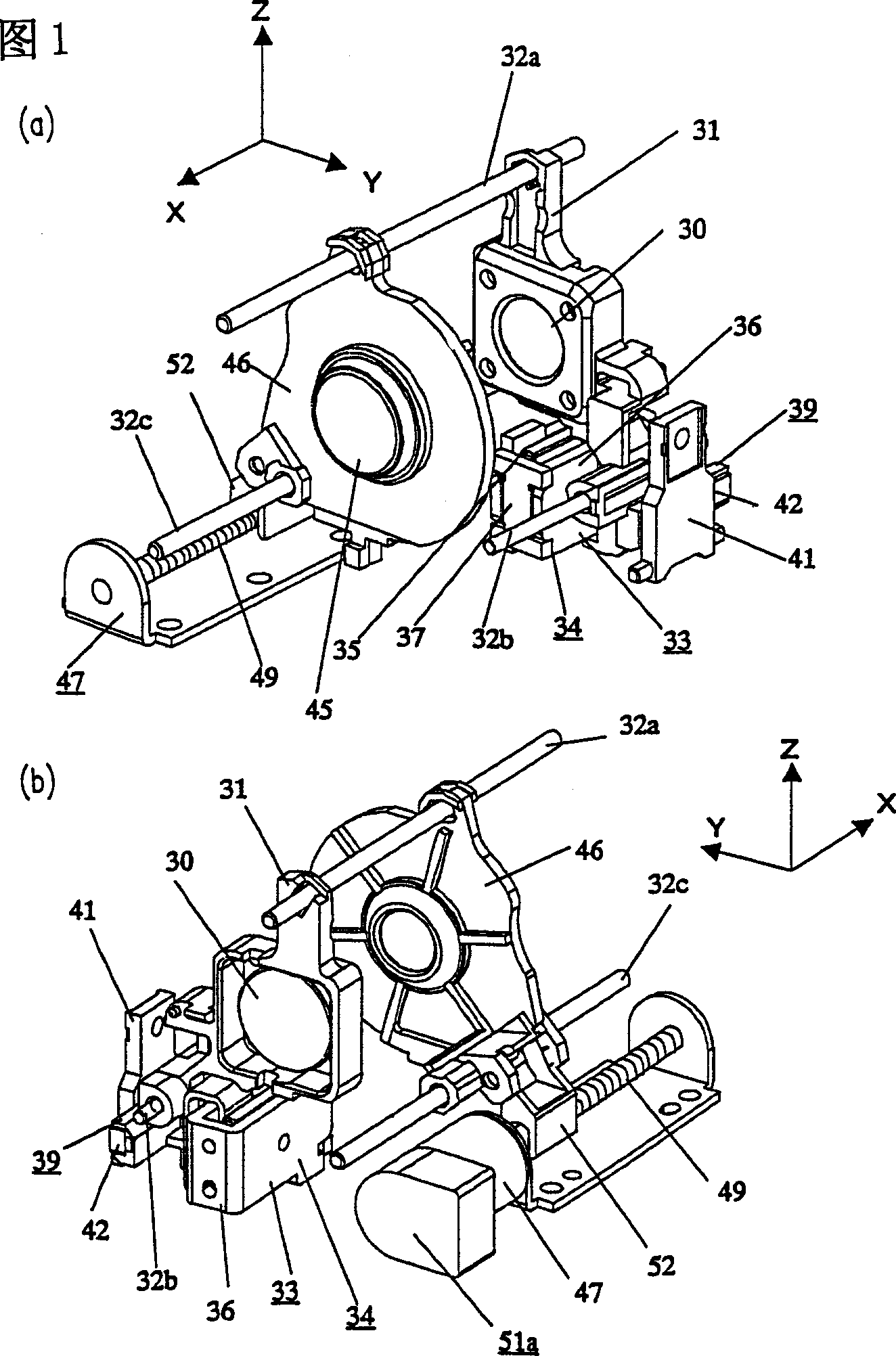
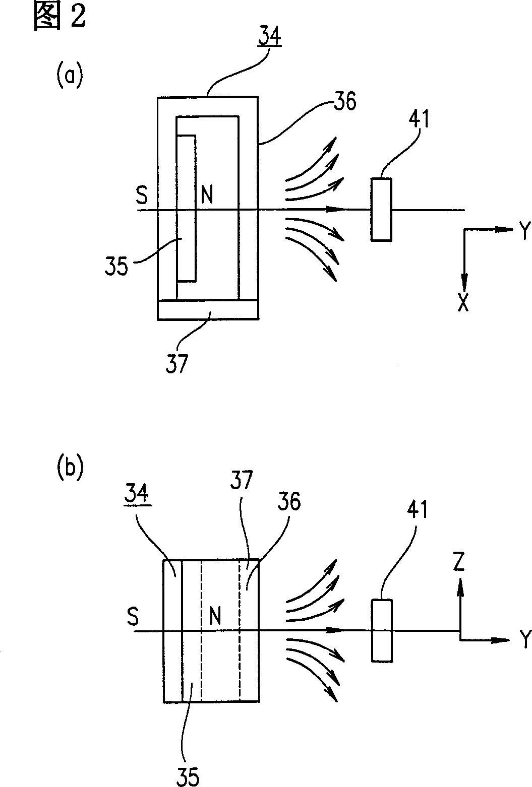
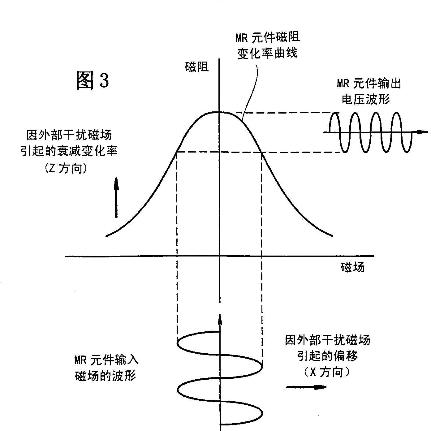
[0060] A lens barrel according to Embodiment 1 of the present invention will be described below by referring to FIGS. 1 to 6 . 1 is a schematic perspective view of a lens barrel according to Embodiment 1 of the present invention, which includes a linear actuator and a stepping motor. Figure 2 is a schematic diagram of the principle of a beam of magnetic flux leaking from the lens barrel. Fig. 3 is a graph showing a magnetoresistance change characteristic of an MR element. Fig. 4 is a schematic perspective view of a position detecting section equipped with an MR element. Figure 5 is a simplified schematic diagram of a beam of magnetic flux leaking onto a stepper motor with an encoder. Figure 6 is a schematic diagram of the principle of a beam of magnetic flux leaked to the magnetic sensor according to Embodiment 1 of the present invention.
[0061] A focus lens moving frame 31 holds a focus lens group 30 which are directed in parallel to an optical axis. The focus lens movi...
Embodiment 2
[0082] The first lens group for compensating for image vibration when taking images is fixed on a holder 2 that can move along the Z direction shown in FIG. 7 . Hereinafter, the cage 2 is referred to as a pitching frame 2 . By installing a support 2a and a lock pin 2b on the opposite side of the support 2a, the pitch moving frame 2 can smoothly move through the two pitch axes 3a and 3b. An electromagnetic actuator 6p is also housed below the pitching mobile frame 2 .
[0083] The electromagnetic actuator 6p includes a coil 7p fixed on the pitch moving frame 2, a magnet 8p and a yoke 9p mounted on the fixed frame 10 as described later. The opposite sides of the yoke 9p have projections 9pa. The fixing frame 10 is provided with engaging holes 10pa capable of engaging the projections 9pa, and they are arranged substantially parallel to the direction in which the tilting movable frame 2 moves smoothly. Thus, the yoke 9p is fixed to the fixing frame 10 without adhesive or the ...
Embodiment 3
[0098] Next will refer to Figures 10 to 13 A third embodiment of the present invention will be described. Figure 10 is a schematic perspective view of a lens barrel according to Embodiment 3 of the present invention, which includes an image vibration compensating device and a linear actuator. Fig. 11 is a schematic structural view of a yoke in a linear actuator. Figure 12 is a simplified diagram of a beam of magnetic flux of a magnet in a displacement actuator of an image vibration compensation device. Figure 13 is a simplified diagram of a beam of magnetic flux of the magnet in the linear actuator according to Embodiment 3 of the present invention. The components described above are denoted by the same reference numerals, and their descriptions are omitted.
[0099] The shift unit 20 in Embodiment 3 is the same as that described in Embodiment 2. For simplicity, the fixing frame 10 of the displacement unit 20 is omitted in FIG. 11 . The pitch magnet 8p, the swing magn...
PUM
 Abstract
Description
Claims
Application Information
 - Generate Ideas
- Intellectual Property
- Life Sciences
- Materials
- Tech Scout
- Unparalleled Data Quality
- Higher Quality Content
- 60% Fewer Hallucinations
Browse by: Latest US Patents, China's latest patents, Technical Efficacy Thesaurus, Application Domain, Technology Topic, Popular Technical Reports.
© 2025 PatSnap. All rights reserved.Legal|Privacy policy|Modern Slavery Act Transparency Statement|Sitemap|About US| Contact US: help@patsnap.com