
Heat-resistant filter layer, filter body, and its production method

A technology of filter layer and filter body, which is applied in the direction of separation method, filter separation, membrane filter, etc., can solve the problems of lack of position or space, and achieve the effect of avoiding vibration or shaking, avoiding loosening phenomenon, and firm combination

Inactive Publication Date: 2007-01-24
EMITEC EMISSIONSTECHNIK
View PDF3 Cites 0 Cited by
  • Summary
  • Abstract
  • Description
  • Claims
  • Application Information

AI Technical Summary

Problems solved by technology

It is very important that there is as large a volume as possible in the universal filter arranged in the car floor, so as to ensure that the particles that have not been converted have a long residence time in the filter, so as to achieve high efficiency, while for the installation close to the engine situation where there is not enough position or space

Method used


Image

  • Heat-resistant filter layer, filter body, and its production method
  • Heat-resistant filter layer, filter body, and its production method
  • Heat-resistant filter layer, filter body, and its production method

Examples


Embodiment Construction

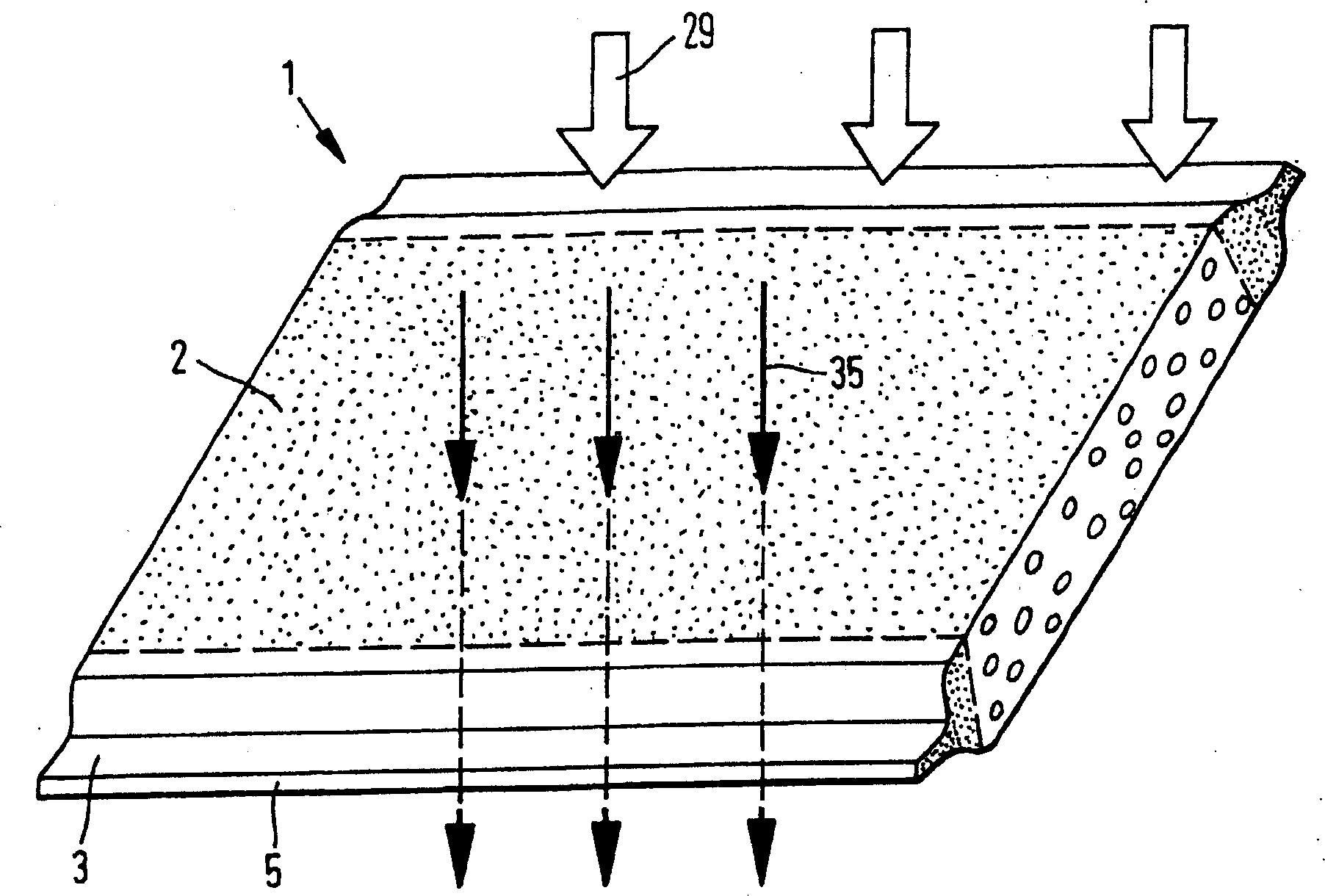
[0057] figure 1 An embodiment of a filter layer 1 according to the invention is shown schematically in perspective, which is permeable for a fluid in at least one filter segment 2 (indicated by flow direction 35 ). The filter layer 1 is made at least partially of a porous material (see filter segment 2 indicated by dashed lines) and has two edge regions 3 adjacent opposite edges 5 . The edge regions 3 are compressed by a pressing force 29 (indicated by arrows), so that they have a reduced layer thickness 4 compared to the filter section 2 . The compression is symbolized by pores or cavities shown in the sectional view, which are shown to be significantly smaller in the edge region 3 than in the filter section 2 .

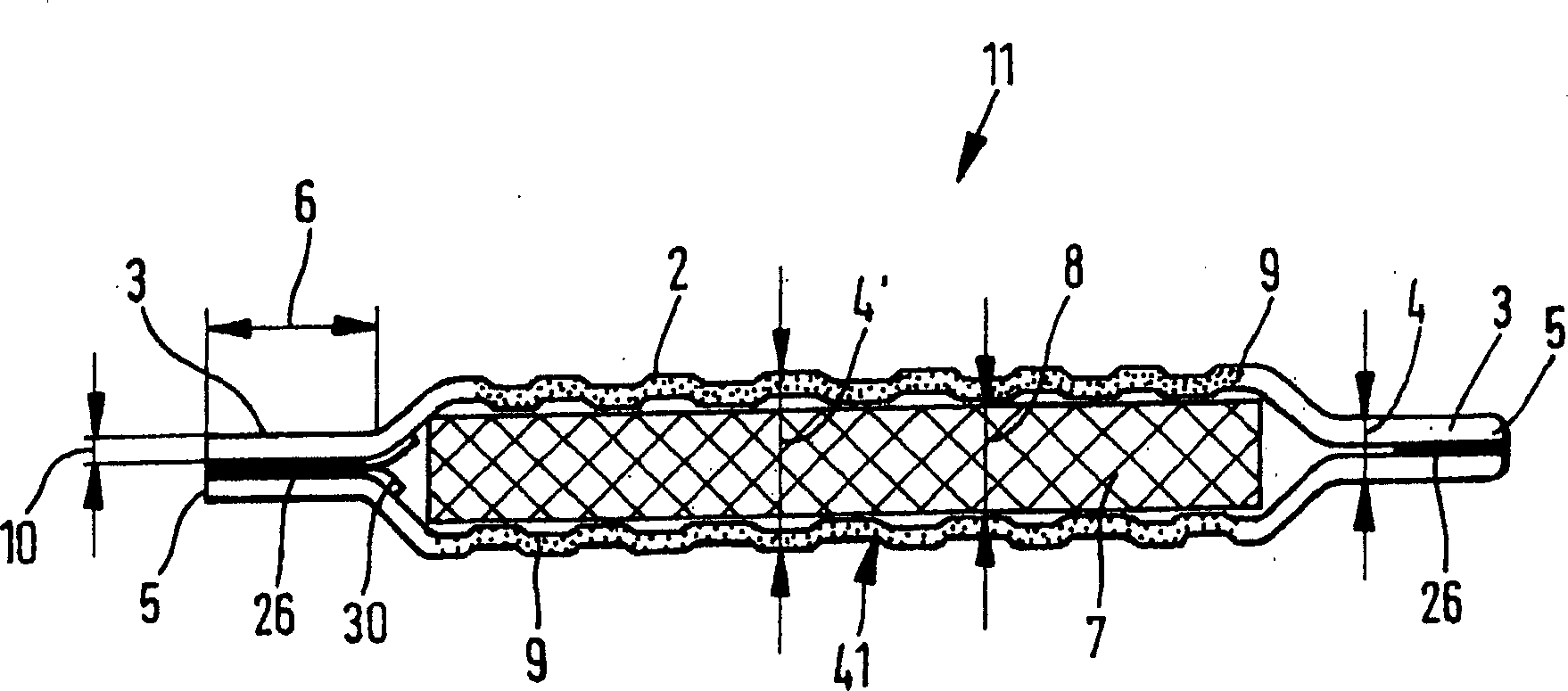
[0058] figure 2 A further embodiment of a filter layer 1 designed as a sandwich structure 11 is schematically shown in cross-section, wherein the filter layer has two metal layers 9 forming an outer shell around the fiber layer 7 . The metal layers 9 each have ...


PUM

PropertyMeasurementUnit
diameteraaaaaaaaaa
thicknessaaaaaaaaaa

Abstract

Within the framework of the purification of exhaust gases of mobile internal combustion engines, filter materials are subjected to particularly high thermal and dynamic conditions. As a result, it is advantageous to use these filter materials together in a stable and durable composite. To this end, the invention provides a heat-resistant filter layer made of a material through which fluid can at least partially flow and which has at least one filter section and at least one edge area. A layer thickness that differs from that of the at least one filter section is provided in the at least one edge area. The invention relates also relates to a corresponding filter body and to a method for the production thereof.

Description

technical field [0001] The invention relates to a heat-resistant filter layer made of at least partially fluid-permeable material, a filter body with at least one such heat-resistant filter layer, and a method for producing such a filter body. Such filter bodies are used in particular to purify the exhaust gases of internal combustion engines for vehicles in automobile construction. Background technique [0002] Looking at the new license plates in Germany, it can be established that a total of one third of all newly licensed vehicles in 2000 had a diesel engine. Here this portion is traditionally considerably higher than, for example, in France and Austria. This increase in interest in diesel vehicles is attributable, for example, to the lower fuel consumption and currently lower diesel prices, but also to the improved driving properties of such vehicles. Diesel vehicles are also very attractive from an environmental point of view because of their significantly lower CO2 ...

Claims


Application Information

Patent Timeline
Patent Type & Authority Patents(China)
IPC IPC(8): B01D46/10B01D39/20F01N3/02B01D39/14B01D46/00B01D46/24B01D46/52F01N3/022F01N3/035F01N3/28F01N13/02F02B37/00
CPCB01D2275/10F01N2013/023F01N13/02F01N2013/026F01N2330/04F01N3/0226F02B37/00F01N3/2821F01N2330/02F01N3/0222B01D2279/30F01N3/035B01D46/525B01D46/0001F01N2330/321F01N2330/10F01N2240/20F01N13/009F01N13/0093F01N13/0097Y10S55/28Y10S55/30B01D39/20B01D46/10F01N3/02
Inventor R·布吕克J·霍格森
Owner EMITEC EMISSIONSTECHNIK
Learn More