Two beam optical switch and attenuator and method of use

An optical switch and optical waveguide technology, applied in optics, optical components, instruments, etc., can solve the problems of optical fiber coupling, signal transmission capacity waste, optical fiber cannot be used, etc., to achieve simple search algorithm, shorten search time, improve The effect of optical properties

Inactive Publication Date: 2007-02-28
约翰 G 伯杰 +1
View PDF14 Cites 0 Cited by
  • Summary
  • Abstract
  • Description
  • Claims
  • Application Information

AI Technical Summary

Problems solved by technology

In such a switch, the ferrule holding the fiber must be rotated up to 180 degrees to couple a pair of fibers and move the end face angles 180 degrees out of phase, causing a mismatch and consequent insertion loss
[0014] Another disadvantage of the design of US5,438,638 is that the fiber capacity is limited
[0017] The structure of US5,438,638 prevents the fiber near the center of the input beam from coupling with the fiber near the center of the output beam
Consequently, the innermost fibers of the two bundles cannot be used, thus resulting in a waste of their signal transmission capacity

Method used


Image

  • Two beam optical switch and attenuator and method of use
  • Two beam optical switch and attenuator and method of use
  • Two beam optical switch and attenuator and method of use

Examples


Embodiment Construction

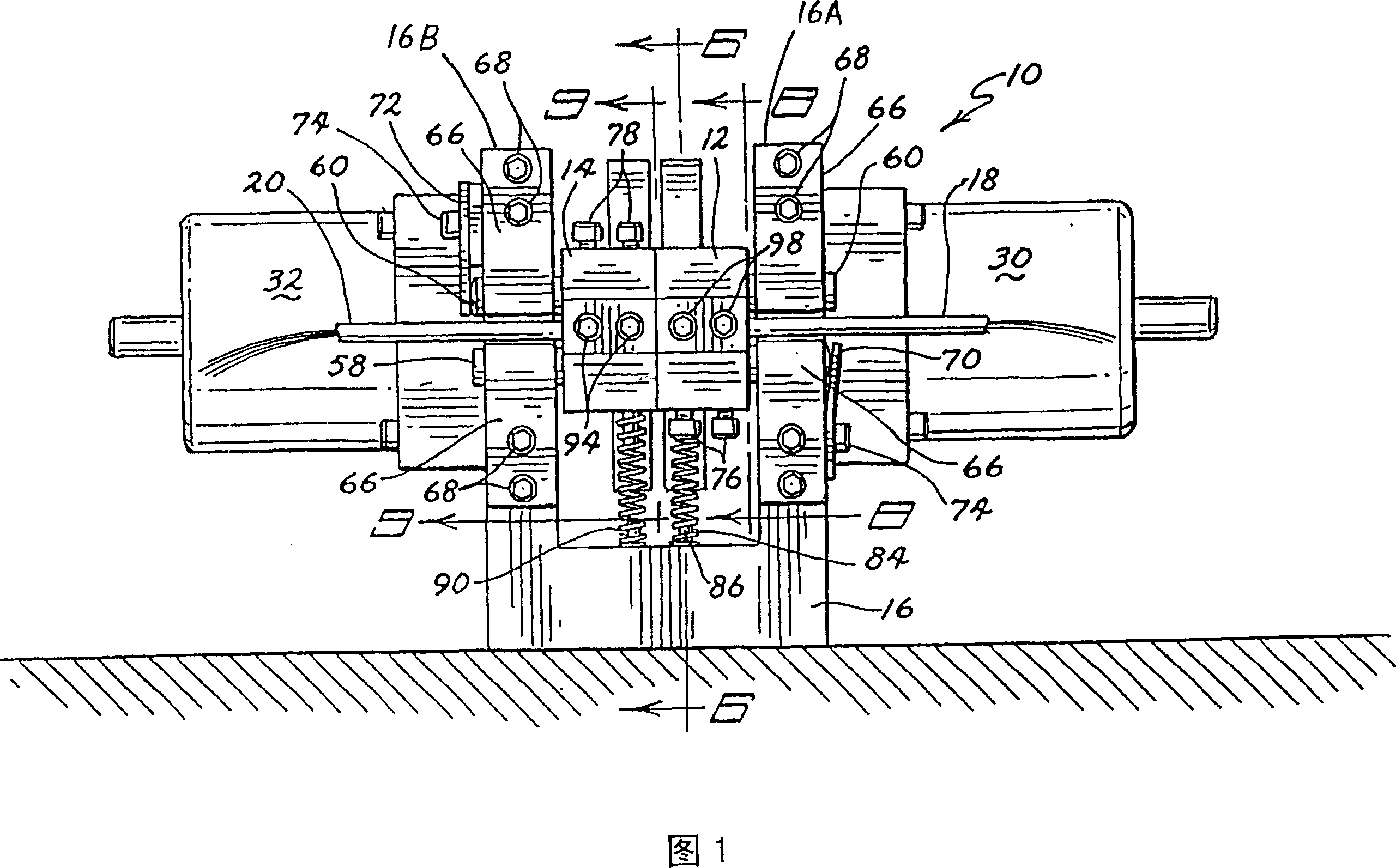
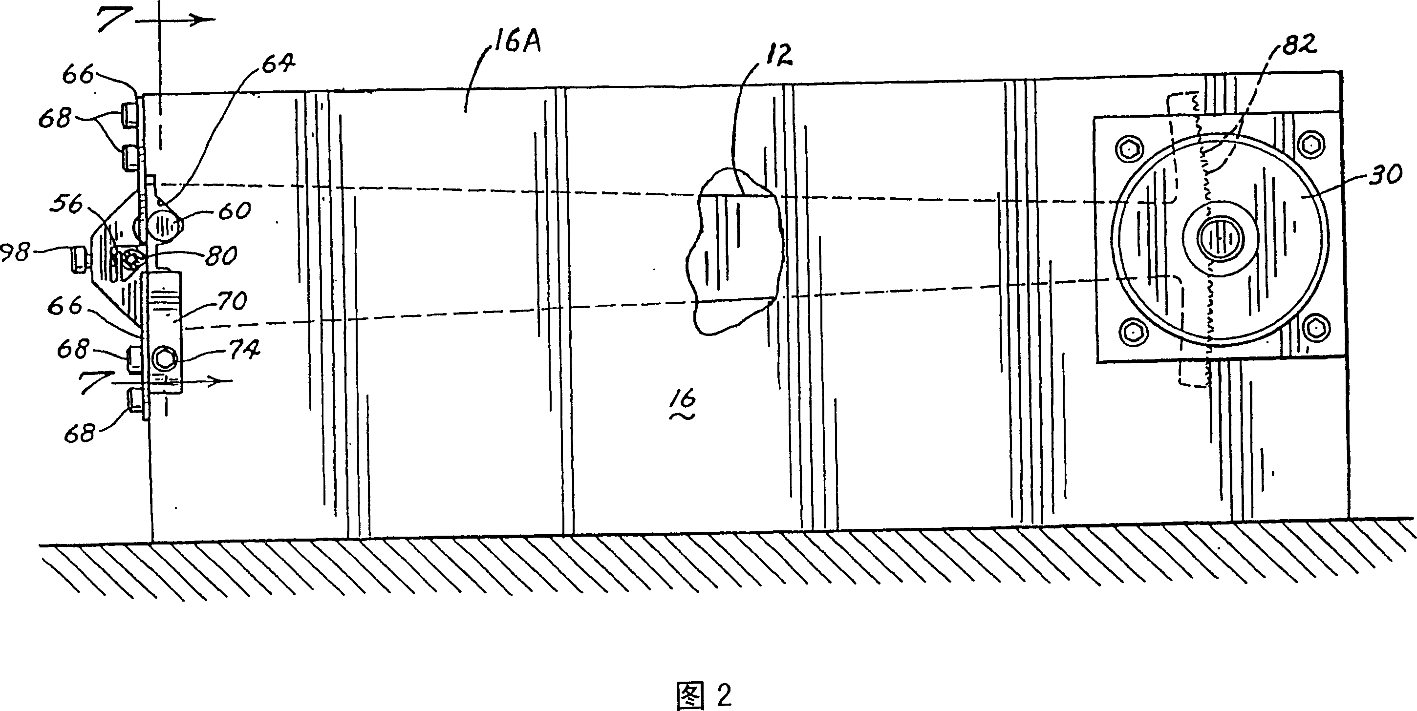
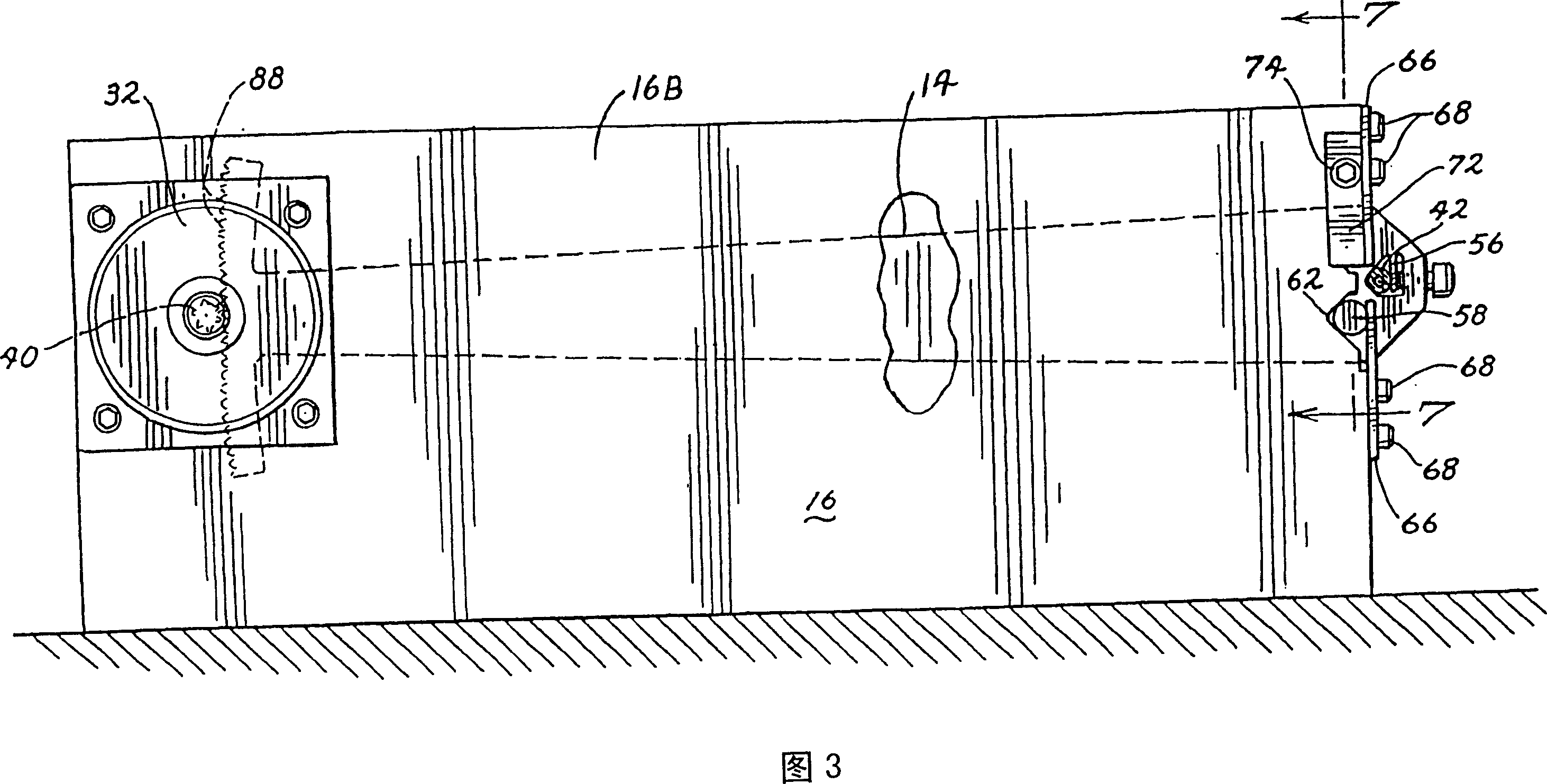
[0047] Referring to the drawings, and in particular to FIGS. 1-11 , a preferred embodiment of a dual beam optical switch is indicated at 10 . As shown, the switch 10 includes four main component groups or sections. As shown in FIG. 1, the base portion includes a base 16 and springs 84, 90 for use as a frame for mounting other components and parts. As shown in Figure 5, the motor, gears and drive electronics form one part. Figure 6 shows the assembly of a mounting beam or beam arm with fiber optic bundles. Figures 10 and 11 show an assembly with a ferrule encapsulating a fiber optic bundle.

[0048] Base and Beam Construction

[0049] The fiber optic switch 10 has a base 16 that acts as a frame for maintaining the proper relationship between the input beam 12 and output beam 14 or beam arms and provides a mounting location for the drive motors 30 and 32 . Base 16 also provides a physical end stop for the movement of each beam 12 and 14 . Said end stop constitutes the start...


PUM


Abstract

An optical switch and attenuator (10, 150, 200) in which any waveguide (48) in an input waveguide bundle (18) may be selectively optically aligned or misaligned with any waveguide (48) in an output waveguide bundle (20). The waveguide bundles (18, 20) are attached to beams (12, 14, 190, 192, 206, 204) that translate the bundles (18, 20) through non-parallel arcs. The optical switch (10, 150, 200) provides high-performance switching and attenuation of any number of input and output waveguides (48).

Description

technical field [0001] The present invention relates to optical devices, and in particular to an optical switch for selectively aligning or aligning any one of a plurality of input optical waveguides with any one of a plurality of output optical waveguides. Misalignment. The invention belongs to intermittent optical switch and optical attenuator [0002] technology field. Background technique [0003] A number of optical switches have been developed for selectively switching optical signals from one waveguide to another across an interface. Regardless of design, insertion loss and reflectivity are important factors in judging the optical performance of a switch. [0004] To minimize insertion loss, the longitudinal, angular, and lateral alignment offsets of the input and output waveguides must be controlled. In the past, lateral offset was the most difficult to control. [0005] Fresnel reflections at discontinuities between input and output waveguides are the dominant ...

Claims


Application Information

Patent Timeline
Patent Type & Authority Patents(China)
IPC IPC(8): G02B6/26G02B6/36G02B26/08G02B6/35
CPCG02B6/3582G02B6/266G02B6/3556G02B6/3504G02B6/3568G02B6/3594
Inventor 约翰·G·伯杰戴维·J·埃蒙斯
Owner 约翰 G 伯杰
Why Eureka
Try Eureka