Radiation fin array cooler

A heat sink cooling and heat sink technology, applied in cooling/ventilation/heating renovation, heat exchange equipment, lighting and heating equipment, etc., can solve the problems of complex mechanical process, reduction of heat sinks, and reduction of the number of heat sinks

Inactive Publication Date: 2007-03-07
HEWLETT PACKARD DEV CO LP
View PDF3 Cites 0 Cited by
  • Summary
  • Abstract
  • Description
  • Claims
  • Application Information

AI Technical Summary

Problems solved by technology

[0006] A disadvantage of the existing mechanical process method is that the kerf widths used to form the air gaps between adjacent fins are parallel due to the kerf wheel used to make the kerf
[0007] A second and related disadvantage of existing mechanical processing methods is that the depth of the cooling fins decreases as the surface area available to efficiently transfer waste heat over the cooling fins to the flowing air
[0008] The third disadvantage is that the number of fins that can be cut out of the cooling surface is reduced
[0009] Finally, the existing mechanical process method is complicated and requires several machining steps, which increases the manufacturing cost of the heat sink

Method used


Image

  • Radiation fin array cooler
  • Radiation fin array cooler
  • Radiation fin array cooler

Examples


Embodiment Construction

[0033] In the following detailed description and in the several figures of the drawings, like parts bear the same reference numerals.

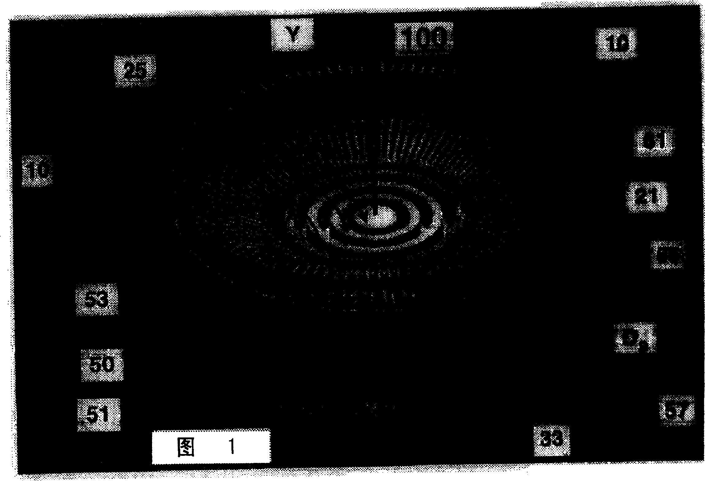
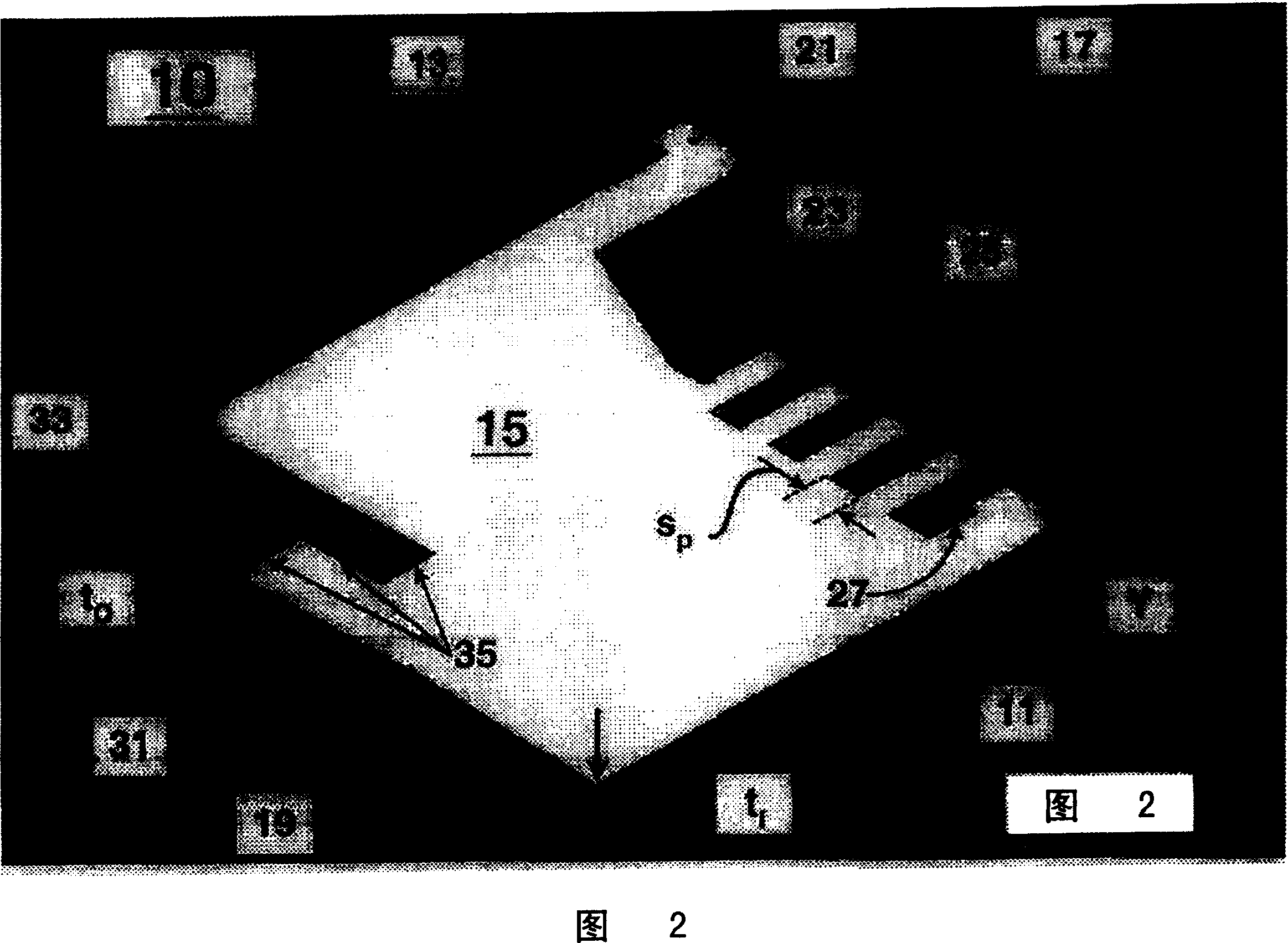
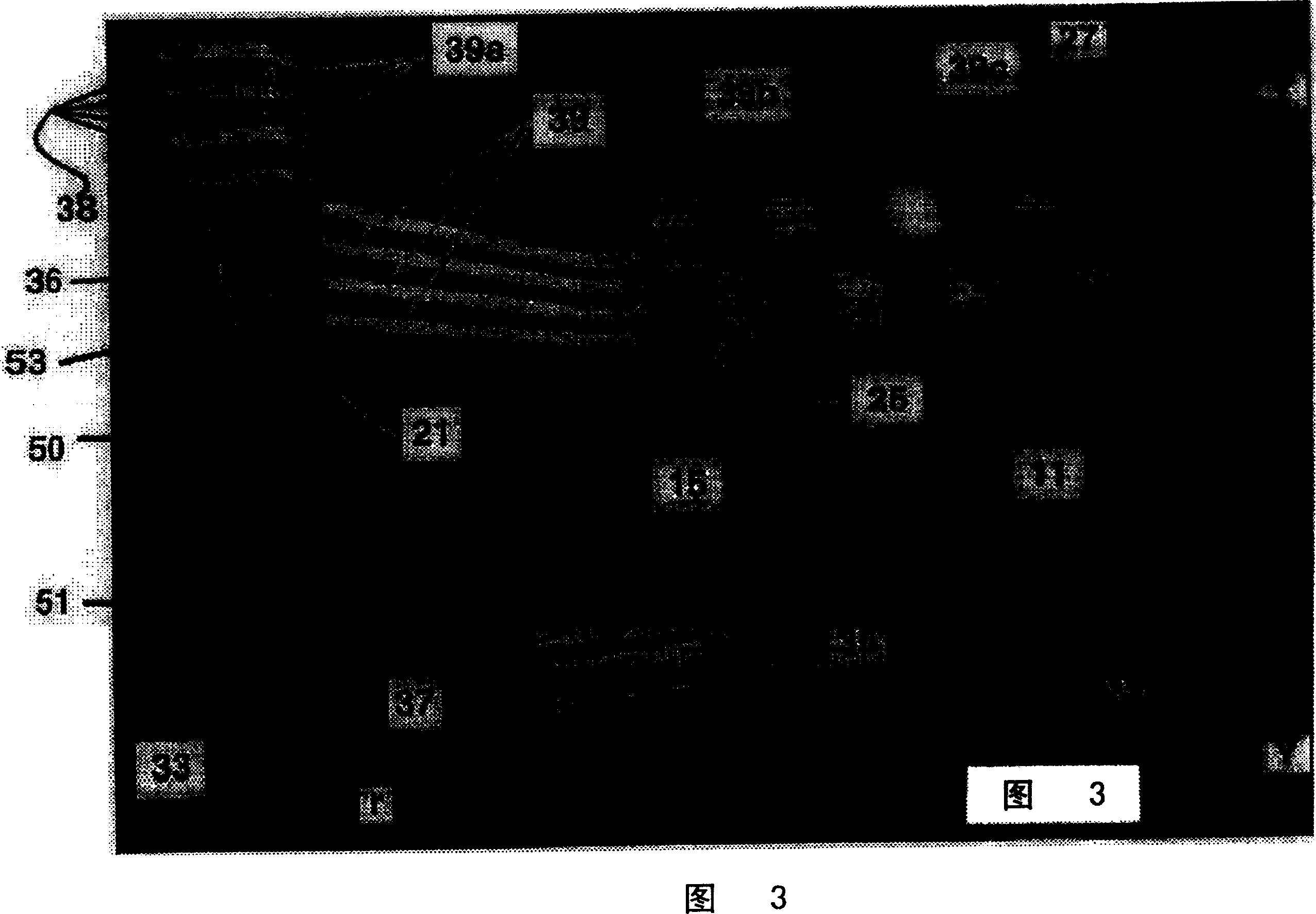
[0034] For purposes of illustration, and as shown, the present invention relates to a discrete fin array cooling system for dissipating heat from a component. The fin array cooling system includes a plurality of separate cooling fins. That is to say, the array cooling system includes a plurality of independent cooling fins, and these cooling fins are combined to form the array cooling system.

[0035] Each separate cooling fin includes an inner edge, an outer edge, and cooling surfaces disposed opposite each other and spaced apart by a gradually decreasing distance from the outer edge to the inner edge. Each cooling fin also includes a leading edge and a trailing edge. The cooling fins are mounted in a radial array, the fins are connected to one another along their respective portions of the cooling surface, and their inner edges are dispose...


PUM


Abstract

An arrayed fin cooling system for removing waste heat from a component is disclosed. The arrayed fin cooling system includes plurality of discrete cooling fins that act as individual heat sinks. The cooling fins are arranged in a radial array so that the cooling fins diverge from one another to define an air path between adjacent cooling fins. Each cooling fin includes a base that is adapted to connect with a surface of the component to be cooled. Waste heat is transferred from the component to the cooling fin via the base. The cooling fins are surrounded at an outer edge by a radial shield that channels an air flow over the cooling fins to maximize the amount of air that passes over the cooling fins. The cooling fins can be manufactured at a low cost using processes such as stamping and forging.

Description

technical field [0001] The present invention generally relates to a fin array cooling system for removing heat from a component. More particularly, the present invention relates to a fin array cooling system comprising a plurality of separate cooling fins arranged in an array in a radial direction, and each cooling fin can be used as a heat sink, thereby Collectively, these cooling fins efficiently dissipate heat from the components. Background technique [0002] Everyone knows that in electronic technology, a heat sink that is in contact with an electronic device should be provided, so that the waste heat generated by the electronic device during operation can be transferred to the heat sink in a thermodynamic manner, thereby cooling the electronic device. With the advent of high-speed clocked electronic devices such as microprocessors (μPs), digital signal processors (DSPs), and application-specific integrated circuits (ASICs), the waste heat generated by these devices an...

Claims


Application Information

Patent Timeline
Patent Type & Authority Patents(China)
IPC IPC(8): H01L23/367H01L23/467H05K7/20G06F1/20F28F3/02H01L21/48H01L23/34
CPCH01L23/467F28F3/02H01L23/3672H01L21/4878H01L2924/0002H01L2924/00
Inventor S·黑德
Owner HEWLETT PACKARD DEV CO LP
Why Eureka
Try Eureka