Supercharge Your Innovation With Domain-Expert AI Agents!

Arm beam type flash raster optical modulator and array

A light modulator and cantilever beam type technology, applied in the field of beam modulation devices, can solve the problems of affecting the diffraction efficiency of gratings, unable to form an area array structure, reducing device contrast, etc., to increase the blazing area, easy area array, and large effective area. Effect

Inactive Publication Date: 2007-03-14
CHONGQING UNIV
View PDF2 Cites 0 Cited by
  • Summary
  • Abstract
  • Description
  • Claims
  • Application Information

AI Technical Summary

Problems solved by technology

Therefore, the contrast obtained by the display based on the above principle is poor compared with the theoretical result.
[0007] (2) It must be ensured that when no voltage is applied, that is, when the device is in the off state, the grid bars are in the same plane to achieve the purpose of completely reflecting the incident light. Otherwise, if the grid bars are not in the same plane, a grating will also be formed. It will produce diffracted light that we don't want to get, which will reduce the contrast of the device display; and when the bias voltage is applied, that is, the device is in the open state, it must be ensured that the movable grid bars in a pixel are all lowered to the same height, which will affect the device. High requirements are put forward for the production precision and craftsmanship
[0008] (3) Due to structural and process limitations, there is a gap w between the two bars g , the gap will affect the diffraction efficiency of the grating
[0009] (4) In order to obtain a suitable offset and a larger effective diffraction area, the length of the grid should be about 100 microns. In this way, the device can only be used for linear arrays. When it is used for display, it needs to use mechanical scanning, which cannot Form an area array structure like DMD

Method used


Image

  • Arm beam type flash raster optical modulator and array
  • Arm beam type flash raster optical modulator and array
  • Arm beam type flash raster optical modulator and array

Examples


Embodiment Construction

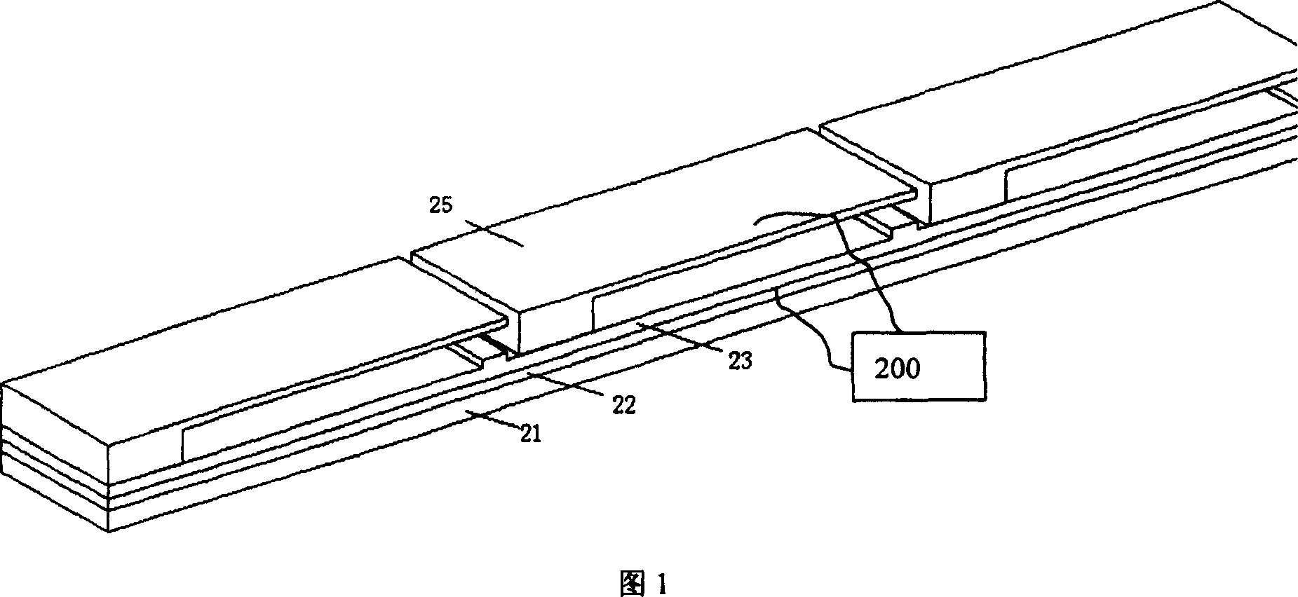
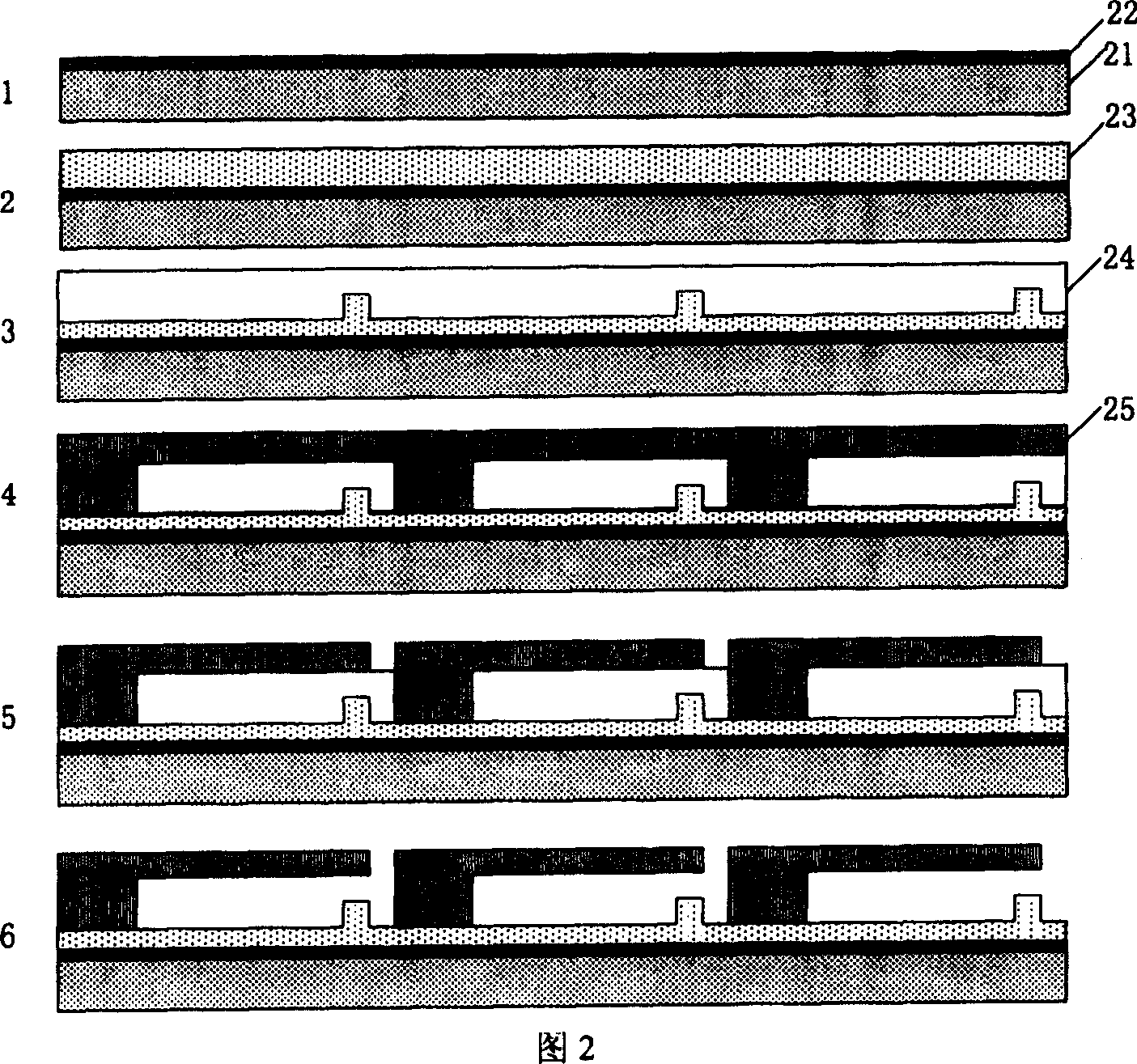
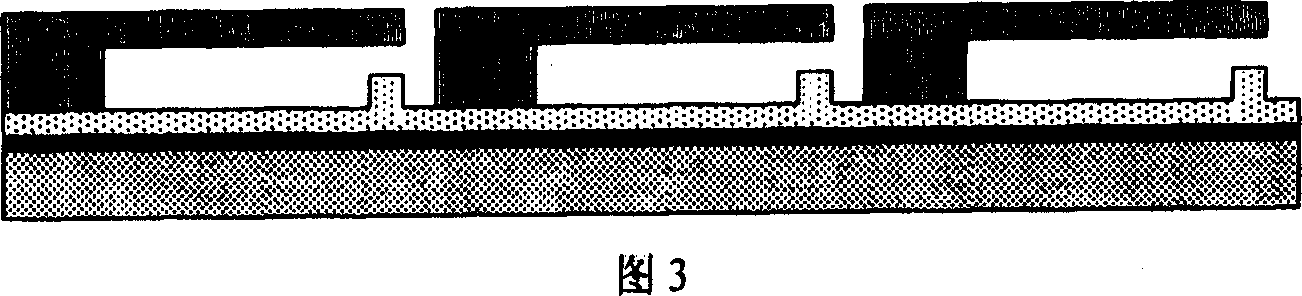
[0025] Referring to Figures 1 and 2, the cantilever beam blazed grating optical modulator has the following composition structure: a substrate 21 and an electric drive device 200, on which a lower electrode layer 22 and an insulating layer 23 are sequentially formed, and a multi-layer suspended above the insulating layer A strip 25 having a reflective surface with a cantilever beam structure, with a gap between the insulating layer 23 and the strip 25, these strips 25 are supported on the base by each end to form a cantilever beam structure . The driving circuit 200 is connected to the upper and lower electrodes through wires, and the driving circuit 200 adopts existing mature technology in the field, and mostly adopts voltage driving. According to different array requirements, use parallel or serial drive mode. At the same time, the electrode lead-out wires of the driving circuit can be obtained while making the structure. When the driving circuit 200 in FIG. 1 applies a pr...


PUM

PropertyMeasurementUnit
lengthaaaaaaaaaa

Abstract

This invention relateds to a cantilever shining grating modulator and the array. It consists of a base planet and an electrical driving device. Orderly form the lower electrode layer and insulating layer on the base planet, many ribbons with reflecting faces above the insulating layer, there is interspaces between the insulating layer and the ribbons, and the ribbons are held by their own end on the insulating layer, at the same time, the metal aluminum film on the ribbon forms the upper electrode, and also is the optical reflecting layer, and forms the cantilever structure, the ribbons are paralleled arranged and form the face array. And the all ribbons are at the same face. Through the side stress, all the reflecting faces are on the first plane. When all the components are in the first plane, the diffraction grating reflects the incident light. When the relating ribbons are at the appointed decline angle, the diffraction grating diffract the incident light, at this moment, the shining grating shines the optical power to the pre-concerted diffraction level.

Description

Technical field: [0001] The invention relates to a light beam modulation device. More particularly, the present invention relates to a cantilever blazed grating light modulator having a substantially planar reflective surface with selectively deformable to provide a blazed diffraction grating. Background technique [0002] The prior art has disclosed a variety of optical modulators based on MEMS technology that can be used alone or together with other modulators, and these modulators include digital micromirror devices (DMDs) and grating light valves (GLVs). [0003] DMD is a modulator composed of millions of deflectable reflective micromirrors manufactured by MEMS technology. The total light extraction efficiency of the DMD imaging device is greatly improved, the modulation speed is fast, and the contrast, brightness and uniformity are excellent. The tight gap of the micromirrors makes the projected image produce a more detailed seamless picture, and the analysis power is ...

Claims


Application Information

Patent Timeline
Patent Type & Authority Patents(China)
IPC IPC(8): G02B26/08G02F1/01G02B26/00
Inventor 黄尚廉张洁付红桥闫许张智海伍艺
Owner CHONGQING UNIV
Features
  • R&D
  • Intellectual Property
  • Life Sciences
  • Materials
  • Tech Scout
  • Unparalleled Data Quality
  • Higher Quality Content
  • 60% Fewer Hallucinations
Learn More