Driving method and circuit for liquid-crystal displaying panel

A technology of liquid crystal display panels and driving methods, which is applied to circuits, transistors, electrical components, etc., and can solve problems such as inaccurate display gray scales, large differences in the number of display units, and crosstalk

Inactive Publication Date: 2007-04-04
TPO DISPLAY
View PDF2 Cites 0 Cited by
  • Summary
  • Abstract
  • Description
  • Claims
  • Application Information

AI Technical Summary

Problems solved by technology

[0009] In the above-mentioned driving method, although the display units are sequentially driven with opposite polarities, in fact, due to the change of the driving sequence, the adjacent display units are not driven sequentially, so it may be due to the positive polarity of the specific display unit group. The difference in the number of polarity display units and negative polarity display units is too large, which causes the common electrode voltage VCOM to be affected by capacitive coupling, resulting in the problem of display grayscale inaccuracy. As shown in Figure 3, the display units in each display unit group The polarities are all the same, so it will affect the level of the common electrode voltage VCOM and cause crosstalk. Therefore, it is necessary to make an appropriate specification for the driving polarity of LCD display panels that share the data electrodes of the display units in the same column.

Method used


Image

  • Driving method and circuit for liquid-crystal displaying panel
  • Driving method and circuit for liquid-crystal displaying panel
  • Driving method and circuit for liquid-crystal displaying panel

Examples


Embodiment Construction

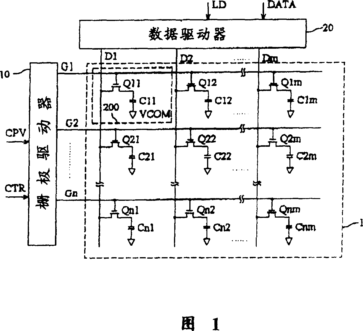
[0044] FIG. 5 is a schematic diagram of an equivalent circuit of a thin film transistor liquid crystal display panel and its peripheral driving circuit according to an embodiment of the present invention. As shown in the figure, the LCD panel 4 is formed by interlacing data electrodes (indicated by D1, D2, ... Dm) and gate electrodes (indicated by G1, G2, ... Gn), and each group of interleaved data The electrodes and gate electrodes can be used to control a display group (display group), for example, the data electrode D1 and the gate electrode G1 can be used to control the display unit group 401, and the data electrode D2 and the gate electrode G1 can be used to control the display unit Group 402. Each display unit group includes a plurality of display units. The display units in the same display unit group are coupled to the same gate electrode and data electrode. Referring to the display unit 200 of FIG. 1, the equivalent circuit of each display unit mainly includes thin ...


PUM


Abstract

A circuit comprises multiple display unit group as each group includes multiple display unit, each display unit group is coupled to corresponding grid electrode and data electrode separately and its display unit is also coupled to the same grid electrode and data electrode. The method provides image signal to data electrode to make number of display unit group in which positive display unit is more than negative display unit be equal to number of display unit group in which negative display unit is more than positive display unit in the same grid electrode and provides scanning signal to grid electrode.

Description

technical field [0001] The present invention relates to a liquid crystal display panel driving circuit and a liquid crystal display, in particular to a data driving method applied to a liquid crystal display panel shared by data electrodes, and proposes a liquid crystal display panel driving circuit capable of eliminating cross-talk And a method for improving picture quality by using the driving circuit. Background technique [0002] FIG. 1 shows a schematic diagram of an equivalent circuit of a thin film transistor liquid crystal display panel (liquid crystal display panel, hereinafter referred to as LCD panel) and its peripheral driving circuits in the prior art. As shown in the figure, the LCD panel 1 is formed by interlacing data electrodes (indicated by D1, D2, ... Dm) and gate electrodes (indicated by G1, G2, ... Gn), and each group of interleaved data The electrodes and the gate electrodes can be used to control a display unit, for example, th...

Claims


Application Information

Patent Timeline
Patent Type & Authority Patents(China)
IPC IPC(8): G02F1/136G09G3/36H01L27/105H01L29/786H04N1/21
Inventor 邱昌明戴亚翔
Owner TPO DISPLAY
Why Eureka
Try Eureka