
Thin film transistor array base plate and patching method thereof

A thin film transistor and array substrate technology, applied in the field of active element array substrate and its repair, can solve the problem of pixel units not being displayed normally, and achieve the effects of improving process yield, improving yield and avoiding damage.

Active Publication Date: 2007-05-23
AU OPTRONICS CORP
View PDF3 Cites 0 Cited by
  • Summary
  • Abstract
  • Description
  • Claims
  • Application Information

AI Technical Summary

Problems solved by technology

[0010] The purpose of the present invention is to overcome the defects existing in the existing thin film transistor array substrate, and provide a thin film transistor array substrate with a new structure. Display problems, thereby providing better process yield, which is more suitable for practical

Method used


Image

  • Thin film transistor array base plate and patching method thereof
  • Thin film transistor array base plate and patching method thereof
  • Thin film transistor array base plate and patching method thereof

Examples


Embodiment Construction

[0077] In order to further explain the technical means and effects of the present invention to achieve the intended purpose of the invention, the specific implementation, structure, The repairing method, steps, features and effects thereof are detailed as follows.

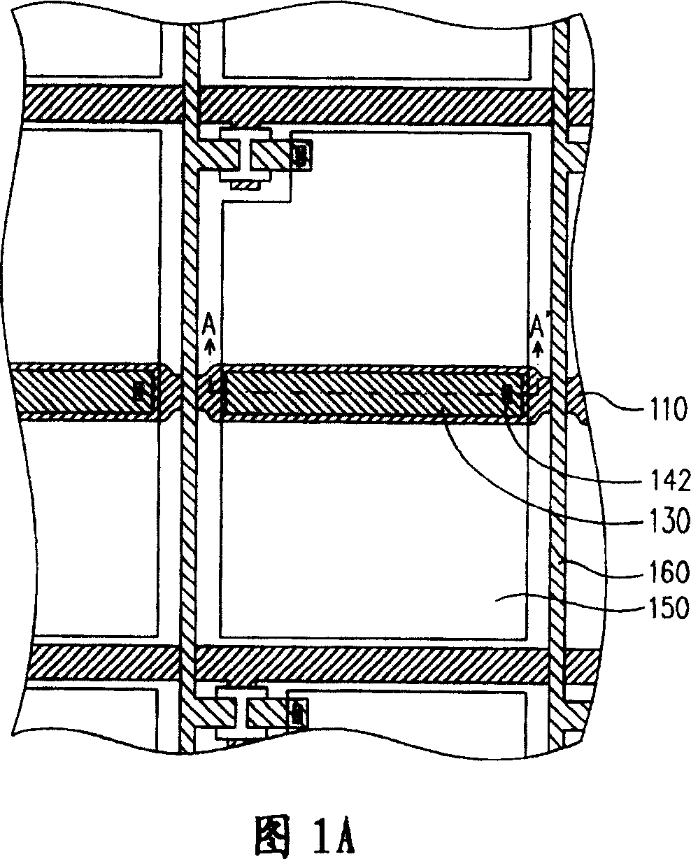
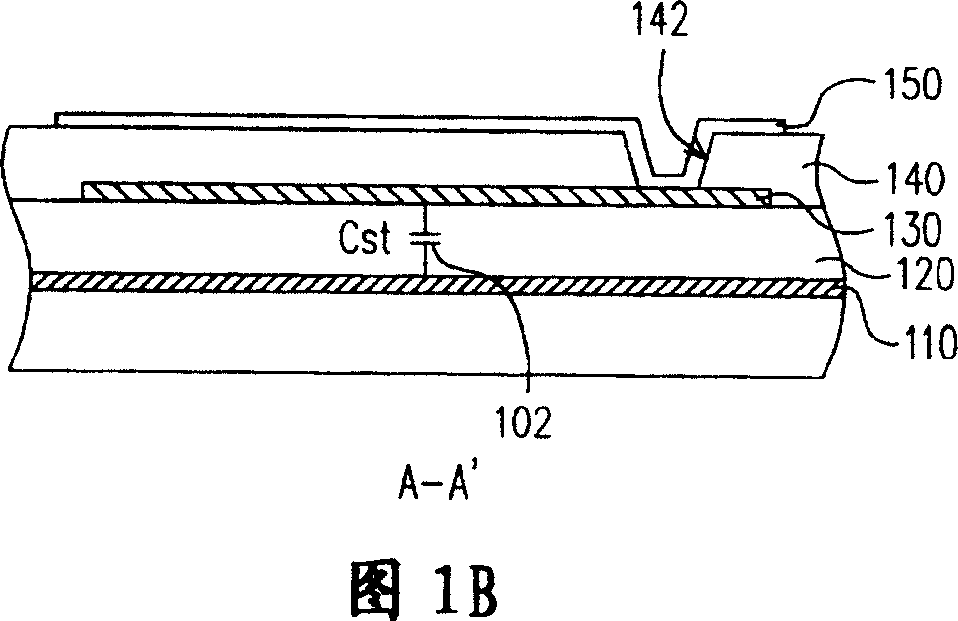
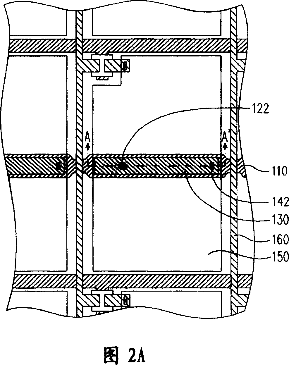
[0078] Please refer to FIGS. 5A and 5B, wherein FIG. 5A is a partial top view of a thin film transistor array substrate of a multi-region vertical alignment liquid crystal display panel of the present invention, and FIG. 5B is A-A of FIG. 5A 'Section diagram. As shown in FIGS. 5A and 5B , the substrate 500 is, for example, a glass substrate on which, for example, a plurality of scanning lines 502 and a plurality of data lines 504 are arranged to divide the substrate 500 into a plurality of pixel regions 500 a. In addition, a plurality of common wirings 506 are disposed on the substrate 500, which are formed simultaneously with the scanning wirings 502, and are made of a metal with good conductivity such as chromiu...


PUM


Abstract

The invention relates to a thin film transistor array base plate and patching method thereof, wherein each picture element of the thin film transistor array substrate is provided with a plurality of upper electrodes, a plurality of capacitors are formed through the corresponding bridging lines, if some of the capacitors are flaw capacitors, only electrical insulation between the flaw capacitor picture element electrode with the picture element electrode of other portion is required, thus other capacitors in the picture element unit can be operated normally, as a result, the picture element unit can be displayed normally.

Description

technical field [0001] The invention relates to an active element array substrate and a repair method thereof, in particular to a thin film transistor array substrate and a repair method thereof. Background technique [0002] A thin film transistor liquid crystal display (TFT LCD) is mainly composed of a thin film transistor array substrate, a color filter array substrate and a liquid crystal layer. The thin film transistor array substrate is composed of a plurality of thin film transistors arranged in an array, and each thin film transistor corresponds to The configuration of the pixel electrode (pixelelectrode) is composed. Thin film transistors are used as switching elements of pixel units, and in order to control individual pixel units, a specific pixel unit is usually selected through a scan line (scan line) and a data line (date line) coupled with the thin film transistor, Appropriate operating voltage is applied to display the display data corresponding to the pixel ...

Claims


Application Information

Patent Timeline
IPC IPC(8): G02F1/136H01L29/786
Inventor 黄韦凯陈奕任蔡承勋王炯宾
Owner AU OPTRONICS CORP
Learn More