
Easily polymerizable compound-treating apparatus using chamfered pot Flamge

A treatment device and a technology for connecting flanges, applied in chemical/physical processes, separation/purification of carboxylic acid compounds, chemical/physical/physicochemical processes, etc., can solve problems such as inability to measure liquid level and internal pressure state, blockage, etc. , to achieve the effect of preventing deterioration of production efficiency and reducing cleaning operation costs

Inactive Publication Date: 2007-06-13
MITSUBISHI RAYON CO LTD
View PDF3 Cites 0 Cited by
  • Summary
  • Abstract
  • Description
  • Claims
  • Application Information

AI Technical Summary

Problems solved by technology

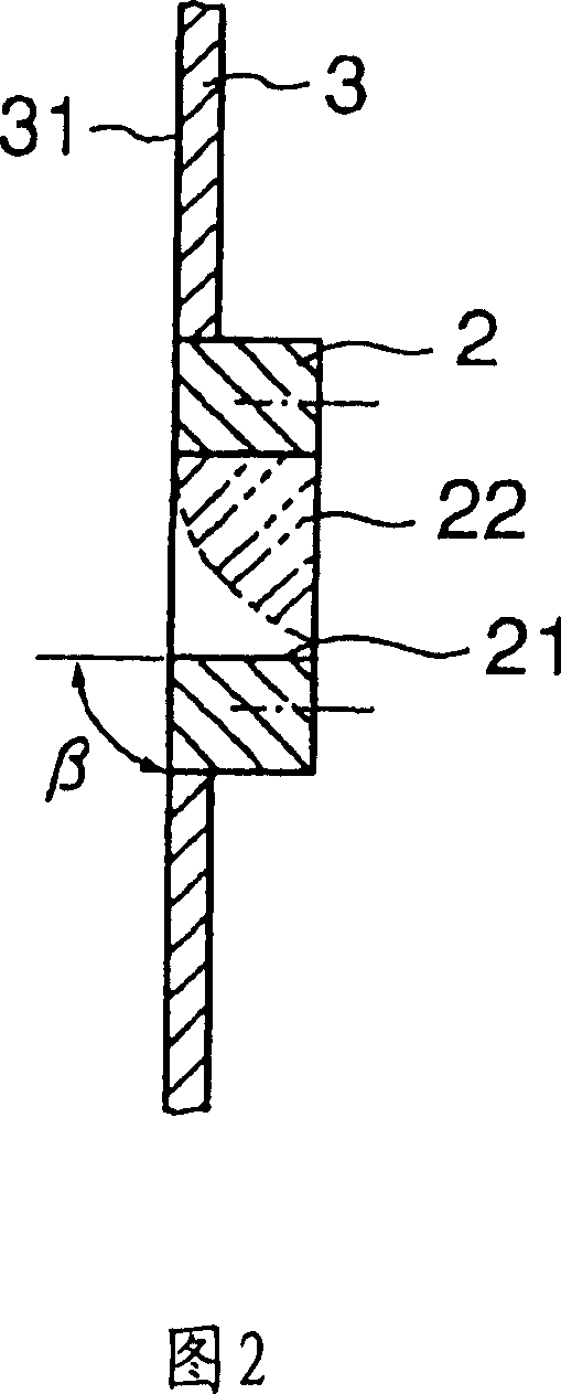
[0006] When the conventional mating flange 2 shown in FIG. 2 is used, and a liquid level gauge, a pressure gauge, etc. are installed on the outer end surface of the mating flange 2, as time goes by, on the part 22 of the through hole 21 , the gas slowly stagnates to form a polymer, which results in the blockage of the through hole 21, resulting in the inability to measure the liquid level and internal pressure, etc.

Method used


Image

  • Easily polymerizable compound-treating apparatus using chamfered pot Flamge
  • Easily polymerizable compound-treating apparatus using chamfered pot Flamge

Examples


Embodiment 1

[0025] The chamfered butt joint flange shown in Figure 1 is used, and the butt joint flange is chamfered with a chamfer angle α=45° and a chamfer width t / total thickness T of the butt joint flange=70%. Machined counter flanges.

[0026] In the middle and lower positions of the main body wall of the stainless steel (SUS316) acrylic acid refining tower, the butt joint flange for the connection of the diaphragm pressure gauge is installed, and at the same time, the same butt joint for the connection of the liquid level gauge is installed. Flange, for acrylic refining.

[0027] The composition of the raw material is 99% by weight of acrylic acid, 1% by weight of heavy substances such as acrylic acid dimer, and continuously operated under the conditions of 2.5kPa at the top of the tower, a temperature of 52°C, a pressure of 5kPa at the bottom of the tower, a temperature of 73°C, and a reflux ratio of 1.0. moon. As a result of in-house testing after the operation was stopped, no p...

Embodiment 2

[0032] The chamfered butt joint flange shown in Figure 1 is used, the butt joint flange is chamfered with a chamfer angle α=35° and chamfer width t / total thickness of the butt joint flange T=50%. Machined counter flanges.

[0033] The butt flange is installed from the lower part of the acrylic acid refining tower made of stainless steel (SUS304) to the main body walls of the first and third stages, and is used as a window connection to purify acrylic acid.

[0034] The raw material composition is 95% by weight of acrylic acid, 5% by weight of light polymers such as acetic acid, and is continuously operated for 6 months under the conditions of 10kPa top pressure and 50°C temperature, 18kPa bottom pressure and 83°C temperature.

[0035] During this period, there is no polymer attached to the window, and the state inside the tower can be observed well. As a result of in-house testing, no polymer adhesion was found on any of the mating flanges.


PUM


Abstract

A lase-of-polymerization handling device having a pat flange installed on the body wall thereof, wherein the end face of a through-hole provided in the pat flange is chamfered on the body wall inner side, whereby, since the accumulation and polymerization of lase-of-polymerization gas can be prevented from occurring at the handling device inner side end face of the pad flange used for connecting instruments such as pressure gauges and liquid level gauges, erroneous indication of the instruments can be eliminated, and safe operation can be performed for a long period.

Description

technical field [0001] The present invention relates to a structure of a butt flange mounted on a main body wall of a processing device such as a reaction tower for preparing easily polymerizable compounds, a distillation tower, or a storage tank for storing solutions obtained therefrom. In particular, the present invention relates to a treatment device for easily polymerizable compounds that prevents gas generated from easily polymerizable compounds and the like from stagnating in through holes provided in the mating flange, and suppresses generation of polymers in this portion. Description of drawings [0002] Fig. 1 is a cross-sectional view of a counter flange of the present invention installed on the main body wall of a treatment device for easily polymerizable compounds, and Fig. 2 is a cross-sectional view of a conventional counter flange installed on a main body wall of a treatment device for easily polymerizable compounds. Background technique [0003] Conventiona...

Claims


Application Information

Patent Timeline
Patent Type & Authority Patents(China)
IPC IPC(8): B01J19/00C07C51/42C07C57/07B01D3/00B01D3/32
CPCB01J19/0053B01J2219/00065B01J2219/00254B01J2219/00067B01J19/002
Inventor 矢田修平强力正康高桥顺一
Owner MITSUBISHI RAYON CO LTD
Learn More