A method of polarization mode dispersion compensation

A polarization mode dispersion and compensation method technology, applied in electromagnetic wave transmission systems, electrical components, transmission systems, etc., can solve the problems of high cost, inability to popularize and apply, and difficult feedback control algorithms, and achieve the effect of reducing compensation costs and simple control.

Active Publication Date: 2007-06-20
GUANGXUN SCI & TECH WUHAN
View PDF2 Cites 0 Cited by
  • Summary
  • Abstract
  • Description
  • Claims
  • Application Information

AI Technical Summary

Problems solved by technology

Adopting this compensation scheme not only needs to formulate a complicated feedback control algorithm, select a high-speed polarization controller and polarization compensation delay device with high quality, but also for the actual WDM system, due to the sales of commercial products of this single-channel PMD compensator The price is between 10,000 and 20,000 US dollars, and the solution will inevitably be unable to be popularized due to the high cost

Method used

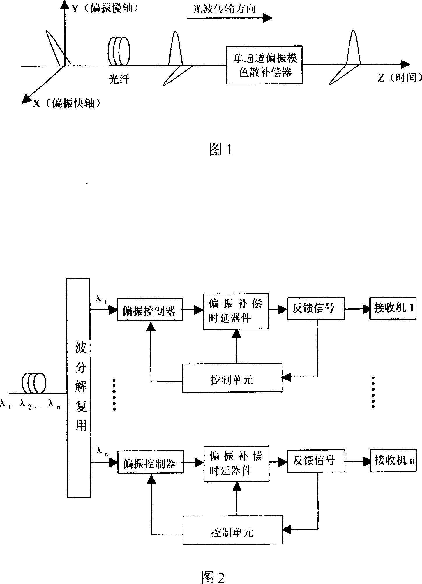
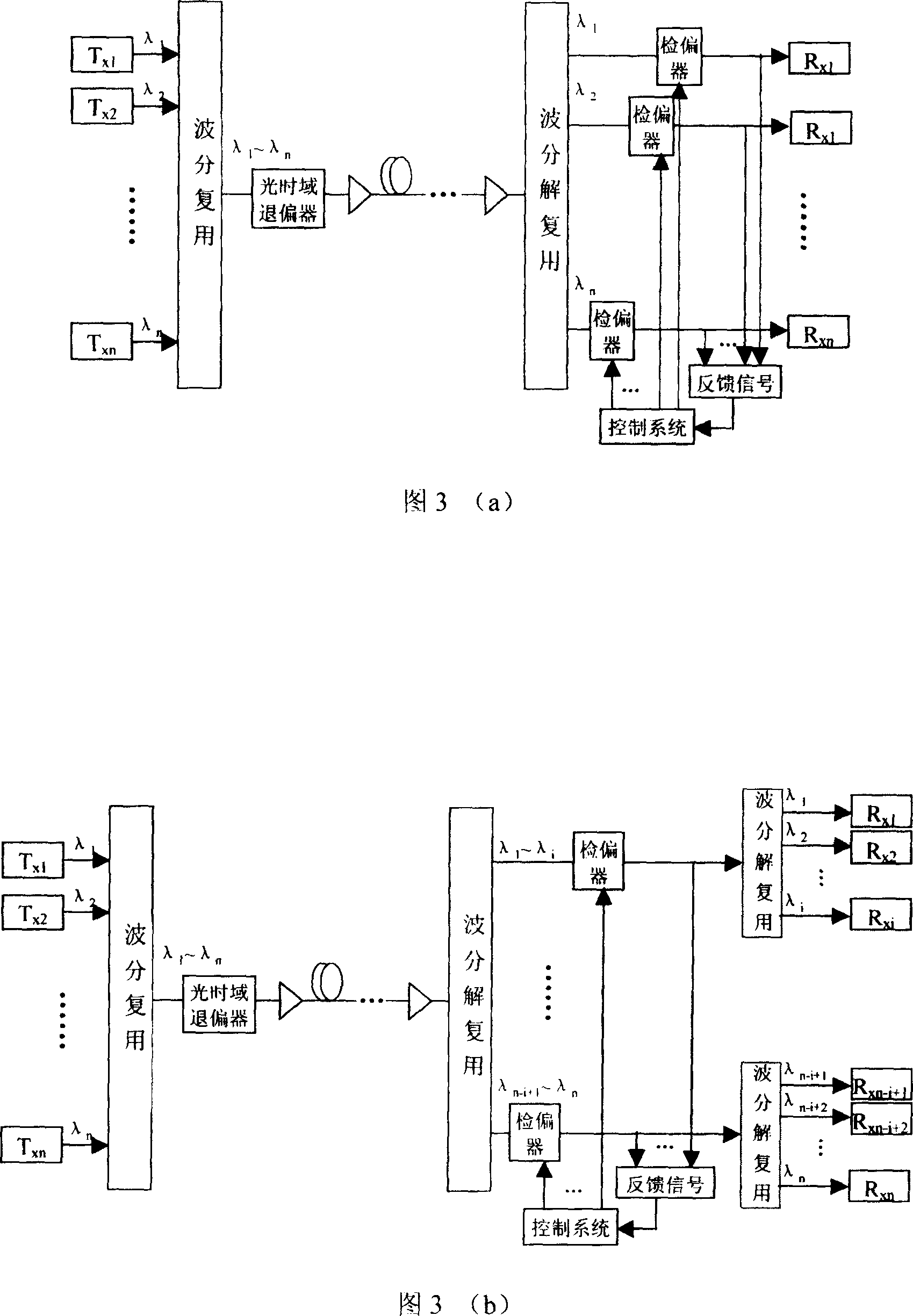
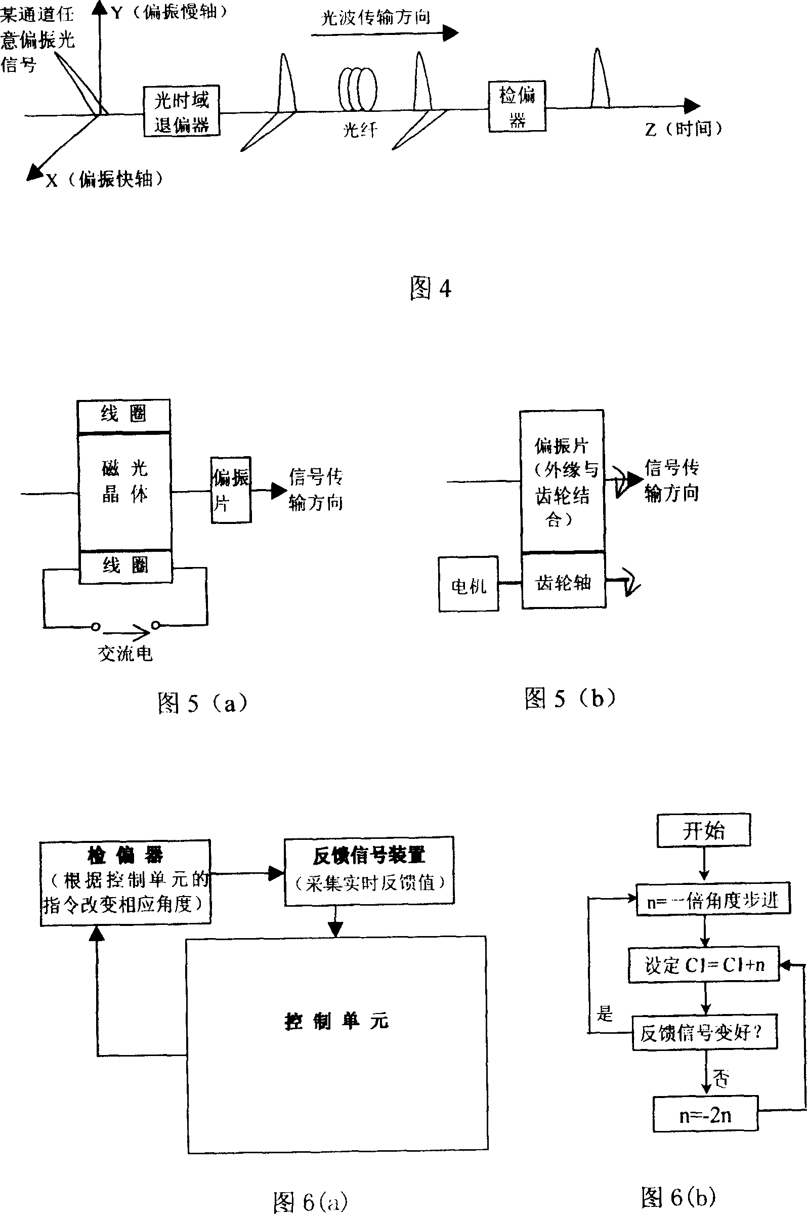

Image

  • A method of polarization mode dispersion compensation
  • A method of polarization mode dispersion compensation
  • A method of polarization mode dispersion compensation

Examples


Embodiment Construction

[0028] The working principle of the present invention is further described below in conjunction with the accompanying drawings and specific embodiments:

[0029] Assume that the Stokes form of the input polarized light of a certain channel in the DWDM system is:

[0030] S in ( β , θ ) = S 0 S 1 S 2 S 3 = 1 cos ( 2 ...


PUM


Abstract

A polarized film dispersion compensation method is used in high speed long distance DWDM fiber communication system with the transmitting rate over 10Gb / S characterizing in applying a high speed depolarizing device to depolarize modulation light signal to natural light in time domain, then the light signal enters into the long distance transmission fiber to be divided into two components with equal energy but having difference group delay along the two cross-polarized main shafts, finally, a polarization analyzer is added to remove a component along the cross-polarize shafts before the light signal enters into the receiver. One set of device is used to compensate PMD of multiple channels.

Description

technical field [0001] The invention relates to a method for realizing dynamic compensation of polarization mode dispersion, which can be used in a high-speed, long-distance dense wavelength division multiplexing (DWDM) optical fiber communication system with a transmission rate of 10Gb / s and above, and is especially suitable for realizing multi-channel optical signal Accurate compensation of polarization mode dispersion. Background technique [0002] For high-speed, long-distance dense wavelength division multiplexing (DWDM) systems with a transmission rate of 10Gb / s and above, a key issue that arises is the polarization mode dispersion of each channel. Due to the influence of the manufacturing process and the external environment, the cross-section of the actual single-mode fiber is no longer an ideal circle, resulting in different propagation constants of the two orthogonal polarization modes in the fiber, and the resulting pulse broadening is called polarization mode di...

Claims


Application Information

Patent Timeline
Patent Type & Authority Patents(China)
IPC IPC(8): H04B10/18H04B10/12H04J14/02H04B10/2569
Inventor 张璐胡强高许远忠刘文罗勇肖远
Owner GUANGXUN SCI & TECH WUHAN
Why Eureka
Try Eureka