
Dummy error addition circuit

An error, emulation technique for electrical components, error prevention, transmission modification based on link quality, etc.

Inactive Publication Date: 2001-12-05
KENWOOD CORPORATION +1
View PDF0 Cites 2 Cited by
  • Summary
  • Abstract
  • Description
  • Claims
  • Application Information

AI Technical Summary

Problems solved by technology

However, no such simulated error adding circuit has been

Method used


Image

  • Dummy error addition circuit
  • Dummy error addition circuit
  • Dummy error addition circuit

Examples


Embodiment Construction

[0017] The simulation error adding circuit of the present invention will be described below according to an embodiment.

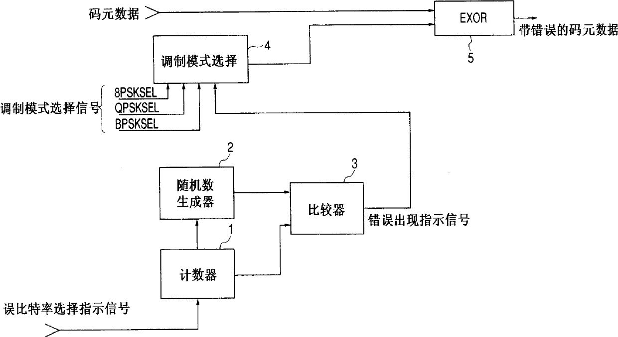
[0018] 1 is a block diagram showing the structure of a simulation error addition circuit according to an embodiment of the present invention, and is configured to correspond to 8PSK modulated by quadrature phase shift keying (PSK) according to an embodiment of the present invention. modulation, QPSK modulation and BPSK modulation as examples to illustrate.

[0019] The purpose of the artificial error adding circuit according to the embodiment of the present invention is to take PSK modulation symbol data as an object, and output modulation symbols randomly added with artificial errors. In digital broadcasting employing the above-mentioned hierarchical transmission system, an error correction code as an outer code is added to and interleaved with information signals for broadcasting such as voice signals and data signals, and a convolutional code as an inner...


PUM


Abstract

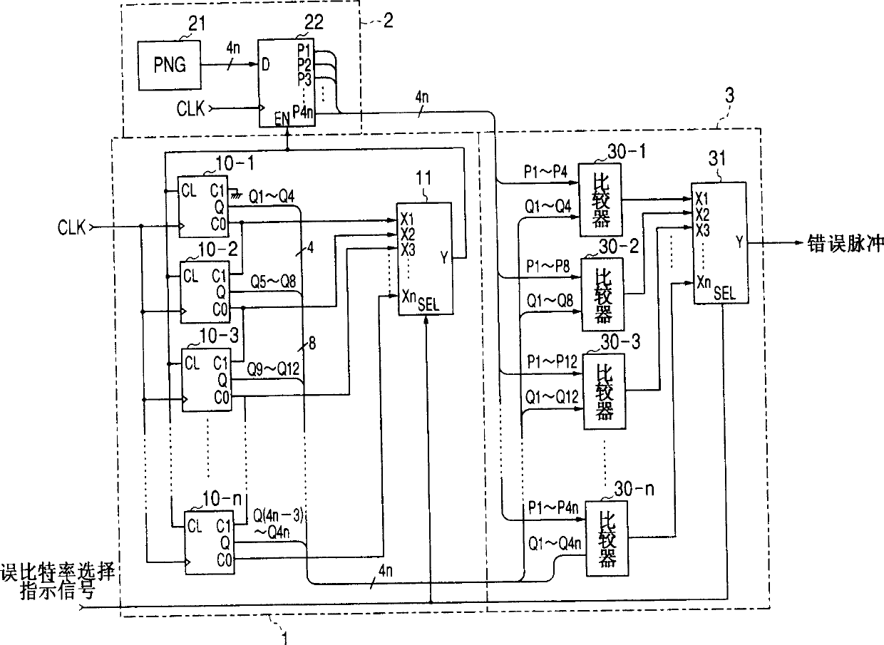
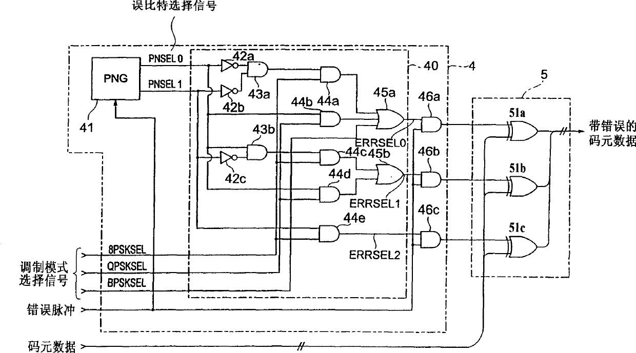
A dummy error addition circuit for adding a dummy error to an orthogonal modulation symbol data, wherein a value based on a specified bit error rate is loaded to count clock signals at a counter(11), a carrier of the counter(11)stores outputs from a PN data generator(21)in a shift register(22), outputs from a PN comparison circuit(3)when stored data agree with count values of the counter(11)are recognized as error pulses, a bit selector(40)randomly selects, on receiving error pulses and based on outputs from a PN data generator(41), bits to which to add errors in an orthogonal modulation data, e.g. a PSK modulation symbol data, at intervals based on a bit error rate, and bits selected from the orthogonal modulation data are inverted in a bit inversion circuit(5)for outputting to thereby add errors.

Description

technical field [0001] The present invention relates to a kind of emulation error adding device, more specifically, relate to a kind of emulation error adding circuit, it can generate a bit error that occurs in the transmission path in an analog way, and is used for decoding the decoder of quadrature modulation signal performance testing. Background technique [0002] In digital broadcasting, it is a hierarchical transmission method that combines multiple transmission methods with different reception carrier C / N ratios, such as a type of time multiplexing using m-phase phase shift keying (PSK) modulation Hierarchical transmission schemes are well known. This approach allows stable digital signal transmission, but is necessarily affected by noise due to bit errors in the case of deterioration of the carrier C / N ratio in the transmission path. [0003] Therefore, in order to test the performance of a decoder in a digital broadcast receiver, a simulated error adding circuit i...

Claims


Application Information

Patent Timeline
Patent Type & Authority Applications(China)
IPC IPC(8): H04L27/22H04L1/00H04L1/24
CPCH04L1/241H04L1/0003H04L1/00
Inventor 石原健一白石宪一新城壮一堀井昭浩
Owner KENWOOD CORPORATION
Learn More