Gas-liquid mixing device

A gas-liquid mixing and atmospheric technology, applied in mixers, mixing methods, fluid mixers, etc., can solve problems such as vibration

Inactive Publication Date: 2002-02-20
今子贤一
View PDF0 Cites 14 Cited by
  • Summary
  • Abstract
  • Description
  • Claims
  • Application Information

AI Technical Summary

Problems solved by technology

However, when this distance is increased, the rotating shaft for connecting the motor mounted on the water surface and the rotating blade becomes longer, and problems such as vibration may occur during rotation, so there is a limit to the length itself.

Method used


Image

  • Gas-liquid mixing device
  • Gas-liquid mixing device
  • Gas-liquid mixing device

Examples


Embodiment Construction

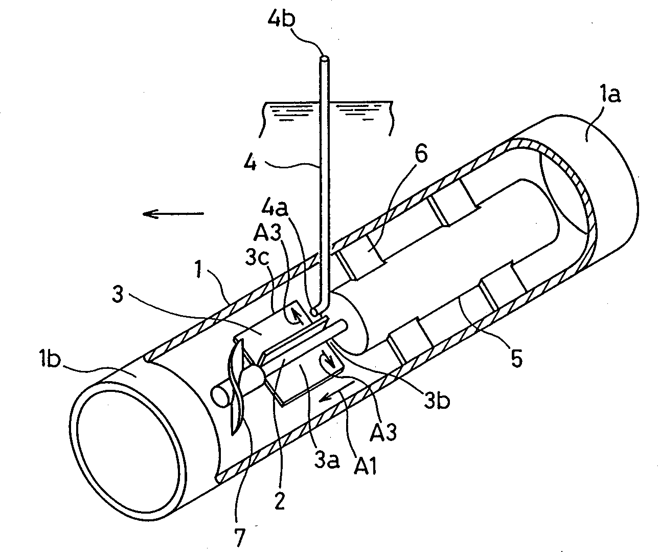
[0021] Such as figure 1 As shown, in a water pipe 1 formed of metal or synthetic resin, etc., a rotating shaft 2 is arranged parallel to its water flow direction A1, and the base end portion 3a of the rotating blade 3 is fixed around the rotating shaft 2, and one end of the air pipe 4 is The opening 4a of the air pipe 4 faces the upstream side 3b near the base end 3a of the rotating blade 3, and the opening 4b at the other end of the air pipe 4 is arranged in the atmosphere outside the water pipe 1.

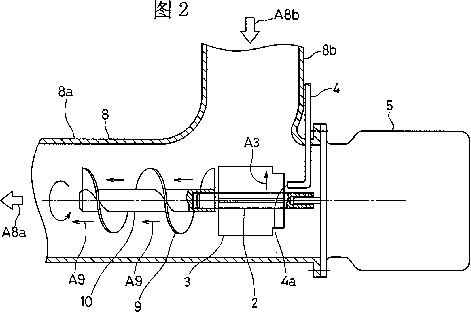
[0022] The motor 5 is directly connected to the rotating shaft 2 of the above-mentioned rotating blade 3, and it is fixed in the same water pipe 1 by the bracket 6, and the rotating blade 3 is rotated by the motor 5, so that the liquid in the water pipe 1 is rotated. At this time, the liquid generates a flow A3 by centrifugal force from the base end 3a toward the front end 3c of the rotating blade 3, and the liquid near the front end 3c is pressurized to a positive pressure, and ...


PUM


Abstract

Gas-liquid mixing device, wherein a rotating shaft is installed in a water tank horizontally along the flow direction of a water tube, a base end part of a rotating vane is fixed to the periphery of the rotating shaft, one end opening part of an air pipe is allowed to face near the base end part of the rotating vane on the upstream side, and the other end opening of it is disposed in the air outside the water tube, whereby such defects that, when the rotating vane disposed at the bottom part of a sewage water tank is rotated by a motor installed on a frame located over the surface of the liquid contained in the sewage water tank, a transmission shaft length is increased to cause vibration, and each part of the device is damaged and its life is shortened are eliminated, and air bubbles caused by the rotating vane are finer so as to increase the solubility of oxygen.

Description

technical field [0001] The invention relates to a gas-liquid mixing device, which is used for water purification in fish farms, live fish transportation and feeding water tanks, swimming pools, or wastewater treatment plants, etc., or for mixing oxygen, Liquid fertilizer, or carbon dioxide gas for mixing and neutralizing in alkaline drainage of tunnels and subway construction sites, and more specifically, relates to a gas in the form of air in the atmosphere mixed in the form of bubbles in the above-mentioned various water liquid mixing device. Background technique [0002] In the conventional gas-liquid mixing device, the motor is installed on a stand installed on the water surface of a water tank or the like, and the upper end of a vertical hollow shaft is connected to the shaft of the motor on the water surface, and an air inlet is formed at the upper end of the hollow shaft. In addition, a plurality of planar blades are arranged radially around the lower end of the holl...

Claims


Application Information

Patent Timeline
Patent Type & Authority Applications(China)
IPC IPC(8): B01F3/04B01F5/02B01F5/04C02F1/78C02F3/12C02F3/20
CPCC02F1/78B01F3/04609C02F3/1294C02F3/206Y02W10/10B01F23/23341
Inventor 今子贤一
Owner 今子贤一
Why Eureka
Try Eureka