Spread-spectrum communication device
A technology of spread spectrum communication and direct sequence spread spectrum, which is applied in the field of portable phones and mobile communication systems, and can solve problems such as characteristic improvement
- Summary
- Abstract
- Description
- Claims
- Application Information
AI Technical Summary
Problems solved by technology
Method used
Image
Examples
no. 1 approach
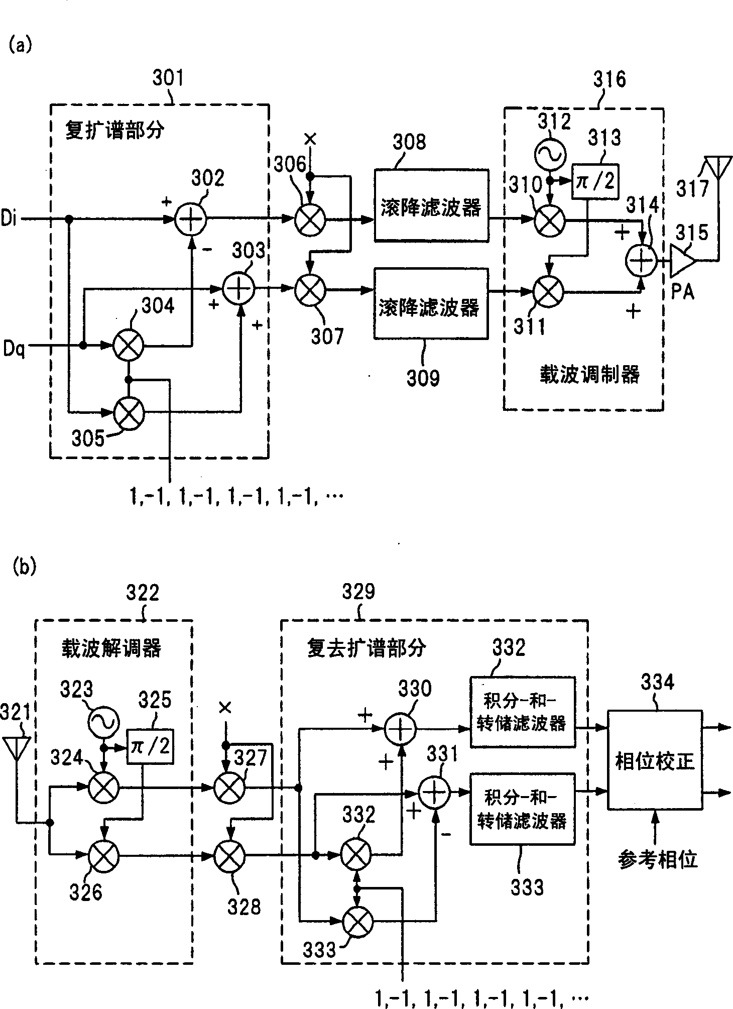
[0036] image 3 is a block diagram of a first embodiment of a spread spectrum communication system according to the present invention, image 3 (a) and image 3 (b) represent the transmitter and receiver, respectively.
[0037] like image 3 As shown in (a), the transmitter includes a complex spread spectrum section 301 for performing complex spread spectrum modulation on the I-phase and Q-phase data Di and Dq of the transmitted signal, and multipliers 306 and 307 for utilizing the The pseudo-random sequence PN generated when the speed is equal to or greater than several times or hundreds of times the symbol rate (k) For data scrambling, roll-off filters 308 and 309 for waveform formation, a carrier modulator 316, a power amplifier 315 and an antenna 317.
[0038] The complex spreading section 301 includes a multiplier 305 for multiplying the I-phase data Di by a complex number sequence in which 1 and -1 alternately appear, and a multiplier 304 for multiplying the Q-phase ...
no. 2 approach
[0052] Figure 6 is a block diagram showing a second embodiment of the spread spectrum communication system according to the present invention. This spread spectrum communication system shows its transmitter including a multiplier 401 for multiplying I-phase data Di by -1, and a switch circuit 402 in place of the complex spread spectrum section 301 of the first embodiment. The other components are the same as in the first embodiment, so the same reference numerals are assigned as in the first embodiment. The switch circuit 402 has switches 403 and 404 controlled by a control signal.
[0053] The transmission signal is separated into I-phase and Q-phase components and input to the switch circuit 402 . The I-phase component is processed through a multiplier 401 to continuously generate its negative phase signal, which is also supplied to a switching circuit 402 .
[0054] The two switches 403 and 404 in the switch circuit 402 are adapted to operate in accordance with a contro...
no. 3 approach
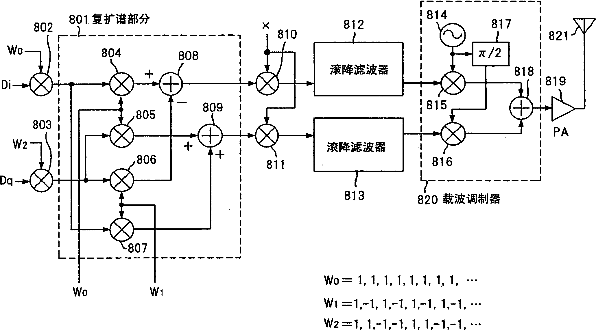
[0057] Figure 8 is a block diagram showing a third embodiment of a spread spectrum communication system according to the present invention, wherein a mapping circuit is placed in image 3 (a) or Figure 6in front of the transmitter as shown. In the first and second embodiments, data is allocated to I-phase and Q-phase components as transmission data Di and Dq. However, for multimedia communications where W-CDMA is expected to be employed, multi-rate transmission, multi-code transmission, etc. are desirable in order to flexibly deal with various data rates.
[0058] Figure 8 Shows a mapping circuit 601 for generating parallel input data D (0) ,D (1) ,D (2) ,…D (N-1) The combination of symbols and input to image 3 (a) or Figure 6 in the transmitter.
[0059] Mapping circuit 601 is configured as many multipliers 603 to 604, 606 to 608, ..., multiple adders 605, 609, ..., and for generating orthogonal code C n circuit. Here, condition 2 is satisfied 1-1 1 A value ...
PUM
 Abstract
Description
Claims
Application Information
 - R&D
- Intellectual Property
- Life Sciences
- Materials
- Tech Scout
- Unparalleled Data Quality
- Higher Quality Content
- 60% Fewer Hallucinations
Browse by: Latest US Patents, China's latest patents, Technical Efficacy Thesaurus, Application Domain, Technology Topic, Popular Technical Reports.
© 2025 PatSnap. All rights reserved.Legal|Privacy policy|Modern Slavery Act Transparency Statement|Sitemap|About US| Contact US: help@patsnap.com


