
Circuit for an Amplifier

a circuit and amplifier technology, applied in the field of circuits for amplifiers, can solve the problems of f typically having relatively large physical dimensions, unable to be integrated into a microchip, and damage to the speaker, and achieve the effect of minimising the player

Active Publication Date: 2012-06-07
TELEFON AB LM ERICSSON (PUBL)
View PDF1 Cites 0 Cited by
  • Summary
  • Abstract
  • Description
  • Claims
  • Application Information

AI Technical Summary

Benefits of technology

[0018]This can provide an output signal for a speaker that contains substantially no DC component. As such, no external capacitors are required to remove the DC component. Moreover, there is no reliance on the provision of two counterbalancing supply voltages to avoid a DC component in the output signal. There is no need therefore to provide additional circuitry to create such a counterbalancing drive voltage, or to provide a positive and negative supply voltage initially.
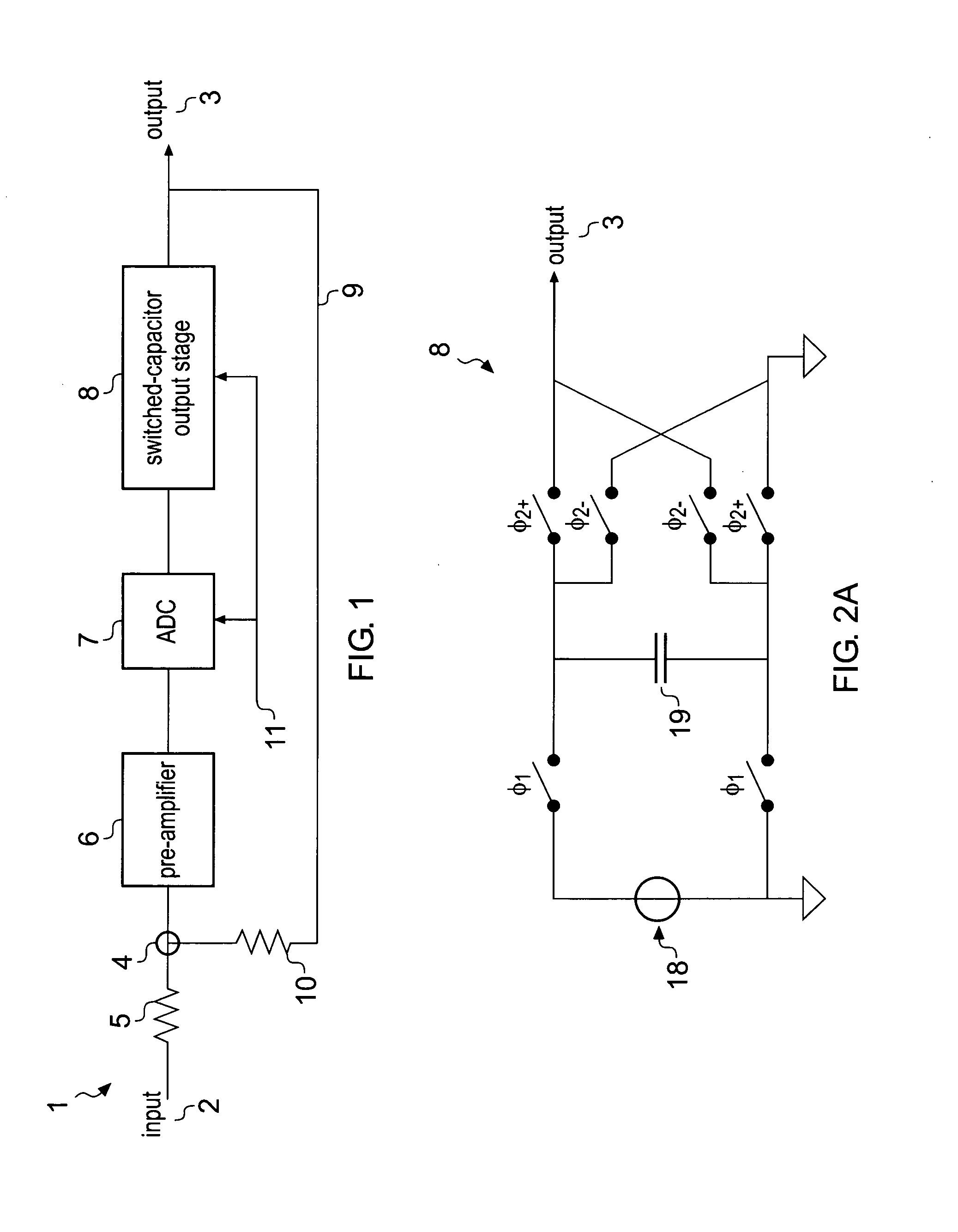
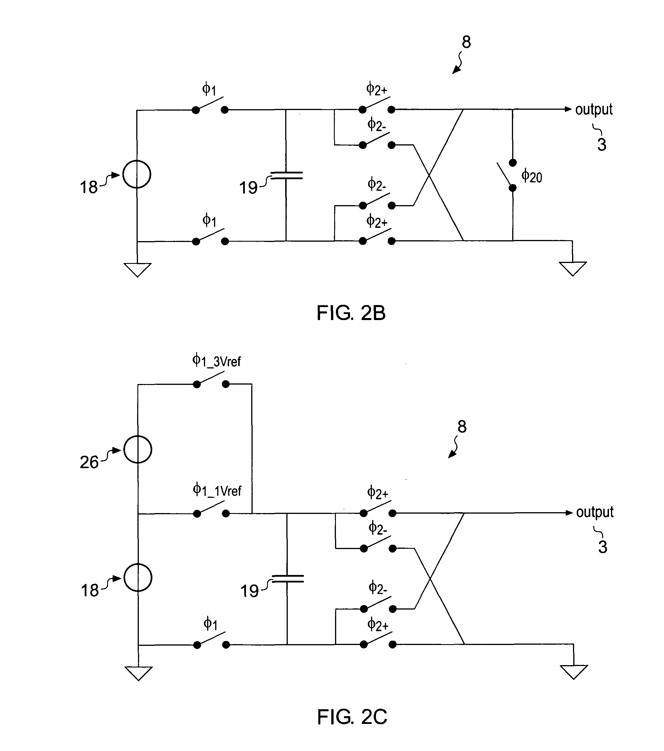
[0021]In preferred examples, the first energy storage element is a capacitive element. However, alternative elements can be used, such as an inductive element. A high symbol rate allows a capacitive element used as the first energy storage element to be effective even if it has only a relatively low capacitance. This assists in the miniaturisation of the capacitive element and therefore the circuit as a whole. In preferred examples, the capacitive element has a capacitance of less than 10 nF. More preferably, the capacitive element has a capacitance of approximately 1 nF.
[0023]The second output stage may have the same features as the first output stage. Likewise, the second charge pulses may be produced in the same way as the first charge pulses. However, the first and second, charge pulses are preferably alternately and sequentially produced. In this way, the first and second charge pulses complement each other and can provide an output signal with a higher density of charge pulses. Moreover, this allows the first energy storage element to be charged while the second energy storage element is discharged, and vice versa.
[0025]Preferably, for a second symbol following a first symbol of the digital signal, the second energy storage element is charged during a period of time in which the first symbol is received and discharged to produce one of the second charge pulses, the polarity of which depends upon the value of the first symbol, during a period of time in which the second symbol is received. In this way, the second energy storage element can be charged before the period during which the second symbol is received. This allows the second energy storage element to be discharged as soon as that period begins.
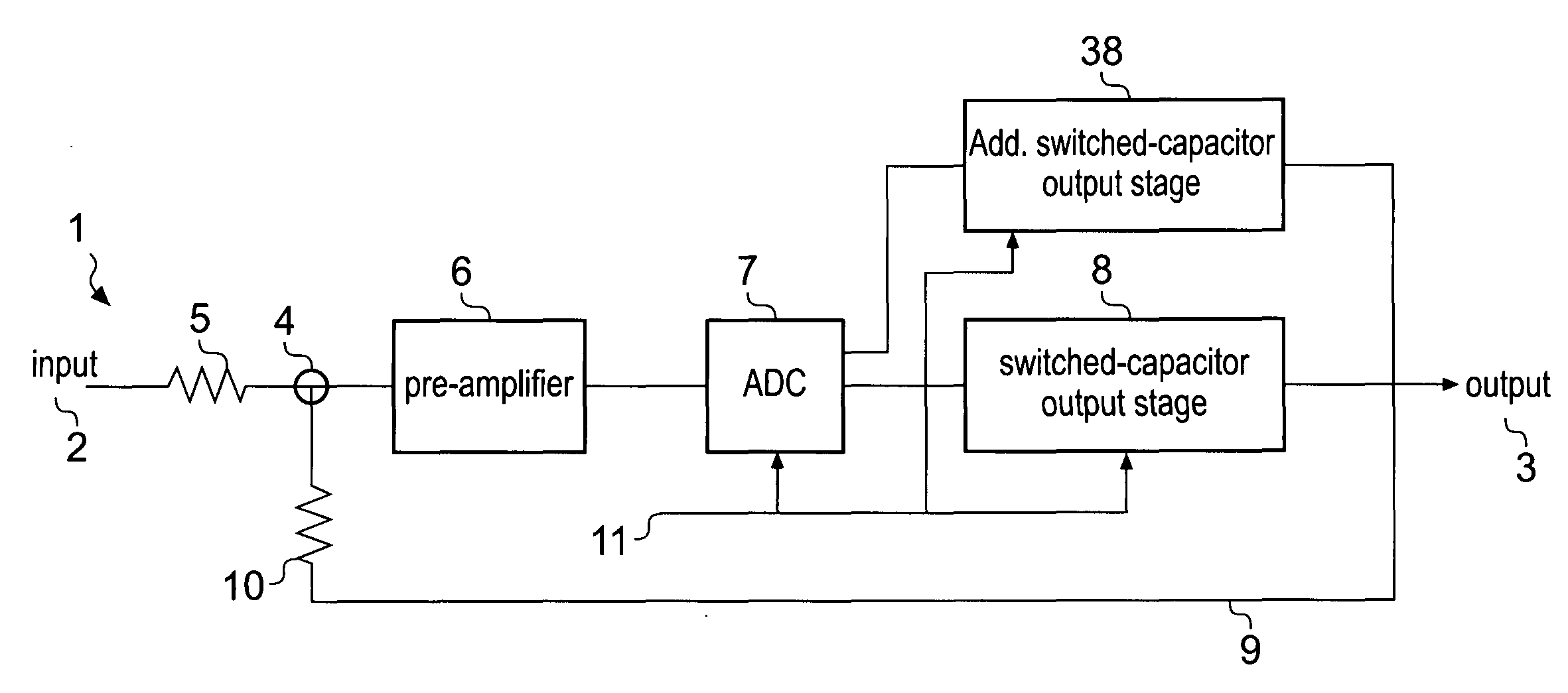
[0032]Preferably, the circuit further comprises a pre-amplifier coupled between the input and the analogue-to-digital converter. Similarly, the method preferably further comprises amplifying the analogue input signal before converting it into a digital signal. The pre-amplifier is effective to improve the gain characteristics of the circuit and method. For example, the pre-amplifier can be used to flatten the frequency response and improve the linearity of the circuit.
[0035]There is further provided a portable audio device comprising an audio amplifier as described above. In other words, the amplifier may be provided in a portable audio device. The portable audio device benefits from the fact that the output signal is provided with no DC component without the need for relatively large capacitors, since this assists in the miniaturisation of the player.

Problems solved by technology

This is undesirable as it may damage the speaker.
Capacitors having capacitance in the order of hundreds of μF typically have relatively large physical dimensions, and cannot be integrated into a microchip.
In the context of a portable audio device, this limits miniaturisation and adds complexity to the device.
However, the DC voltage-to-voltage converter requires additional capacitors and / or inductors which cannot be integrated onto a microchip.
Although this is significantly lower than the capacitance of the in-line capacitor described above, the capacitors still cannot be integrated easily onto a microchip so must be provided external to the microchip like the in-line capacitor.
This approach therefore takes up additional space and does not miniaturise the amplifier to the extent that may be desired.
As a result, there are cost implications in the application of this approach, and also potential instability in the amplifier if the regulation is unsuccessful.

Method used


Image

  • Circuit for an Amplifier
  • Circuit for an Amplifier
  • Circuit for an Amplifier

Examples


Embodiment Construction

[0010]According to a first aspect, there is provided a circuit comprising:

[0011]an input for receiving an analogue input signal;

[0012]an analogue-to-digital conversion stage operable to convert the analogue input signal into a digital signal comprising a plurality of symbols each having one of a plurality of different values; and

[0013]a first output stage coupled to receive the digital signal from the analogue-to-digital conversion stage, the first output stage comprising a first energy storage element and being operable to discharge the first energy storage element to produce first charge pulses in an output signal, the polarity of the first charge pulses depending upon values of the symbols received from the analogue-to-digital conversion stage.

[0014]According to a second aspect, there is provided a method comprising:

[0015]receiving an analogue input signal;

[0016]converting the analogue input signal to a digital signal comprising a plurality of symbols each having one of a plurali...


PUM


Abstract

An amplifier (1) includes an analogue-to-digital converter (ADC) (7) and a switched capacitor output stage (8). The ADC (7) converts an analogue signal into a digital signal containing a sequence of symbols. The switched capacitor output N stage (8) charges and discharges a capacitor to produce charge pulses at an output (3). During discharge, switches selectively couple the capacitor to the output (3) in opposite directions to produce charge pulses of opposing polarity. The values of the symbols in the digital signal are used to decide the polarity of charge pulses. In this manner, amplification can be achieved without introducing a direct current (DC) component to the signal at the output (3).

Description

FIELD OF THE DISCLOSURE [0001]The present disclosure relates to a circuit for an amplifier. In particular, but not exclusively, the disclosure relates to an amplifier for use in a portable audio device.BACKGROUND TO THE DISCLOSURE [0002]Amplifiers used in portable audio devices are typically powered by a power source providing a supply voltage Vdd. An analogue signal representing audio information is input to the amplifier. The amplifier outputs an amplified signal biased midway between the supply voltage Vdd and ground; that is, biased at Vdd / 2. In this way, the amplified signal can extend across the full range of available voltages, or from the supply voltage Vdd to ground, without distortion. Moreover, this approach also ensures that both positive and negative fluctuations in the input analogue signal are represented in the amplified signal.[0003]The amplified signal is output to a speaker, which in the case of a portable audio device is typically contained in headphones. The spe...

Claims


Application Information

Patent Timeline
IPC IPC(8): H03F3/00H03M1/12
CPCH03F3/005H03F3/187H03H19/004H03F2200/375H03F2200/417H03F2200/03
Inventor PUTTER, BAS
Owner TELEFON AB LM ERICSSON (PUBL)
Learn More