
Microfuel cells for use particularly in portable electronic devices and telecommunications devices

a technology of microfuel cells and electronic devices, which is applied in the direction of cell components, final product manufacturing, sustainable manufacturing/processing, etc., can solve the problems of cumbersome battery recharge, short battery life, and difficulty in finding electrical plugs

Inactive Publication Date: 2004-10-07
SAGEM SA +1
View PDF0 Cites 25 Cited by
  • Summary
  • Abstract
  • Description
  • Claims
  • Application Information

AI Technical Summary

Benefits of technology

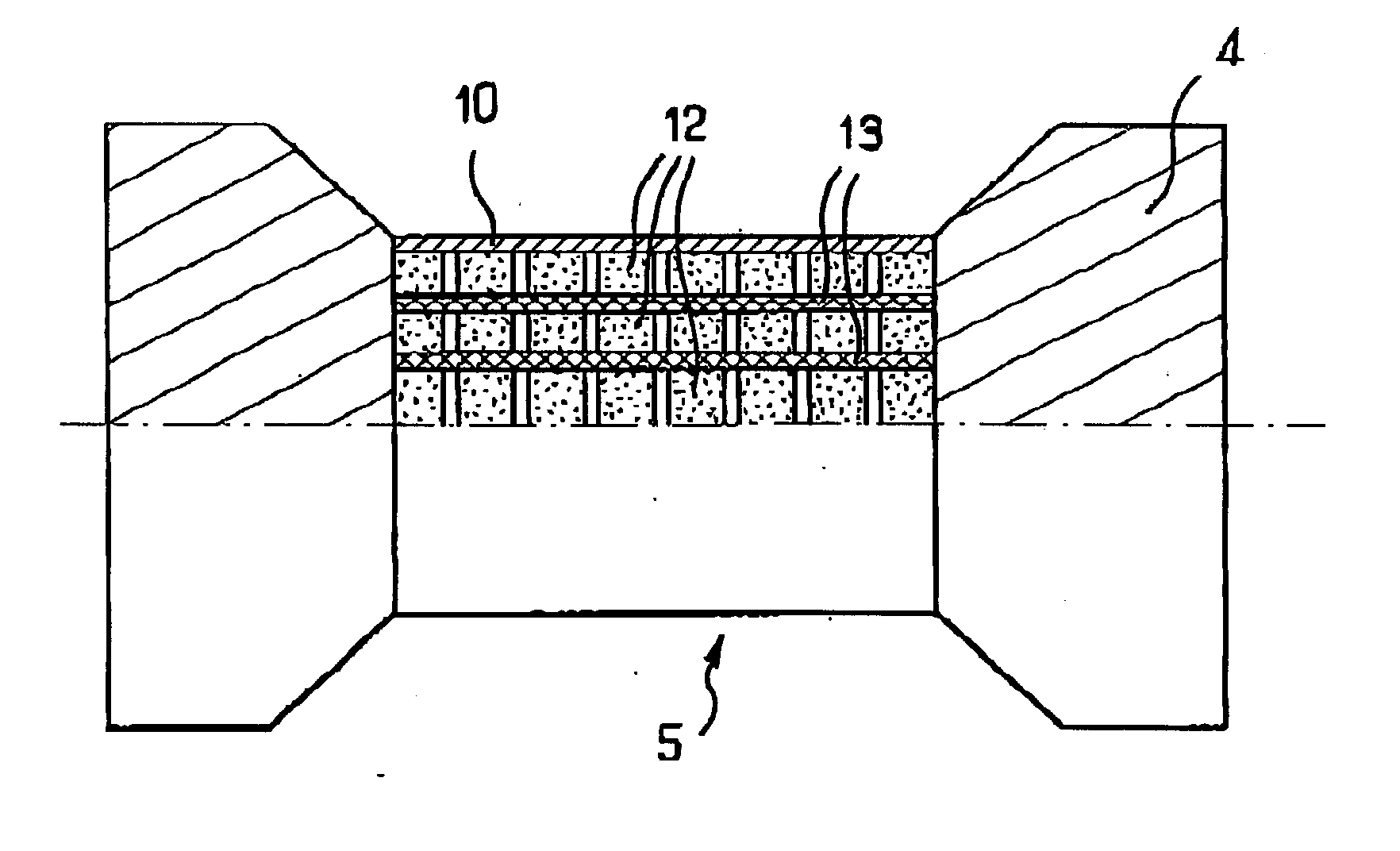
[0015] The semiconductor used as the solid medium of the electrolytic membrane makes it possible to control the porosity percentage and the pore dimensions, which are thus able to constitute a very effective barrier to the water molecules included in the membrane and to the fuel molecules. Moreover, the use of a semiconductor provides surfaces of quality for depositing the electrodes.
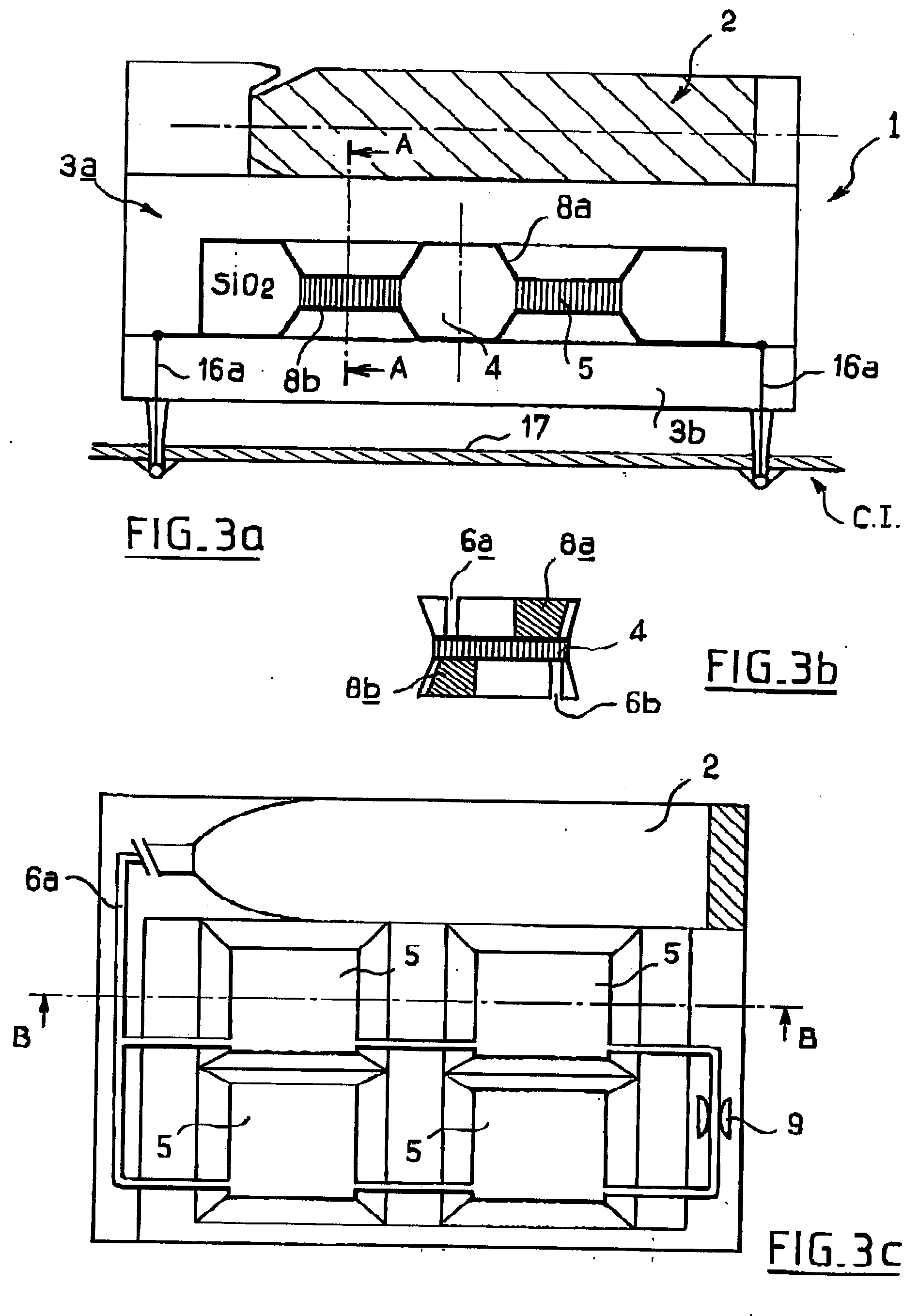
[0029] Because of the low kinetics of the gases generated by the electrochemical reaction, and in order to limit the dimensions of the exchangers responsible for responding to the thermal management of the cell, a micro-pump of MEMS technology may be used. In the same way, a micro-pump which may be of similar technology will be used to advantage in order to ensure the management of the circulation of the air and water. This contribution of active Microsystems helps in the miniaturisation of the device.

Problems solved by technology

However, the life span of batteries is short, and the need for a recharge of the battery is cumbersome.
Indeed, an electrical plug is sometimes hard to find, it is hard to use the portable device during the charging.
Furthermore, the batteries are hard to recycle and are an environmental hazard.
Plus, the batteries are expensive to make.
Compact lithium batteries designed for portable electronic appliances provide an output voltage of about 3 to 4 volts, whereas a basic fuel cell element is not able to develop more than 1 volt.
Lastly, the microcell manufacturing process must comprise a restricted number of operations compatible with a low production cost.
Furthermore, it needs water to operate.
On top of that, the transverse leaks are impossible to control.
It is hard as well to get small devices with this material.
Plus, in these devices, the water contained in the membrane which is required for the transport of the protons, evaporates under the thermal stresses of the operation or the environment.
Additionally, the liquid fuel tends to filter through the membrane, which reduces the efficiency of the cell.
Lastly, the techniques of assembly used to manufacture current microcells are highly hybridised and require a great number of handling operations.
The membranes in this document are in liquid state and make the miniaturization difficult.

Method used


Image

  • Microfuel cells for use particularly in portable electronic devices and telecommunications devices
  • Microfuel cells for use particularly in portable electronic devices and telecommunications devices
  • Microfuel cells for use particularly in portable electronic devices and telecommunications devices

Examples


example 1

[0087] Silicon microporous material is impregnated with Nafion.RTM. 117. One 10 .mu.L drop of Nafion.RTM. perfluorinated ion-exchange resin at 5 wt % solution in a mixture of lower aliphatic alcohols and water is placed on the silicon microporous material so that it wets the inside space of the microporous material by capillary action. Drying is done under controlled atmosphere at 20.degree. C. and 90% relative humidity. This procedure is repeated on the other surface. The microporous material is then treated with hot 3 mol.L.sup.-1 nitric acid over a period of 2 hours then washed in distilled water over a period of two days by means of a Soxhlet. At 25.degree. C. and under 90% relative humidity, a conductivity of 30 mS / cm is obtained.

example 2

[0088] Silicon microporous material is impregnated with Nafion.RTM. 117. One 10 .mu.L drop of Nafion.RTM. perfluorinated ion-exchange resin at 20 wt % solution in a mixture of lower aliphatic alcohols and water is placed on the silicon microporous material so that it wets the inside space of the microporous material by capillary action. Drying is done under controlled atmosphere at 20.degree. C. and 90% relative humidity. The microporous material is then placed in hot 3 mol.L.sup.-1 nitric acid over a period of 2 hours then washed in distilled water over a period of two days by means of a Soxhlet.

[0089] The filling of the porosity with a polyelectrolyte having an aromatic main chain such as polysulfones, polyether sulfones, polyether-ether-ketone, polyphenylene oxide, polyphenylene sulfide, ionic group carriers, sulfonic, phosphonic, carboxylic is also possible. The polyelectrolytes can comprise only one of these functional groups or can combine a plurality of these functional group...

example 3

[0090] 2 g of Udel 3500 @ polysulfone are dissolved in 20 ml of dichloroethane. Trimethylsilylchlorosulfonate is added so as to obtain an exchange capacity of 1.8 moles of protons / kg. After precipitation in ethanol, the polyelectrolyte is dissolved in a 4 / 1 mixture of dichloroethane and isopropanol. Solutions of sulfonated polysulfones are introduced into the porosity of the silicon by capillary action using one 10 .mu.L drop on the surface of the microporous material. The polysulfones used have a sulfonation rate of 1.6 to 1.9 protons per kilogram. After introduction of the polysulfone, conductivities varying between 20 and 70 mS / cm were obtained depending on the sulfonation rate.

[0091] The sulphonation can also be done after the introduction of the polymer in the channels. The filling of the porosity can be done on the basis of a polymer having an aromatic main chain such as polysulfone, polyether sulfone, polyether-ether-ketone, polyphenylene oxide, polyphenylene sulfide. After f...


PUM

PropertyMeasurementUnit
Fractionaaaaaaaaaa
Fractionaaaaaaaaaa
Thicknessaaaaaaaaaa

Abstract

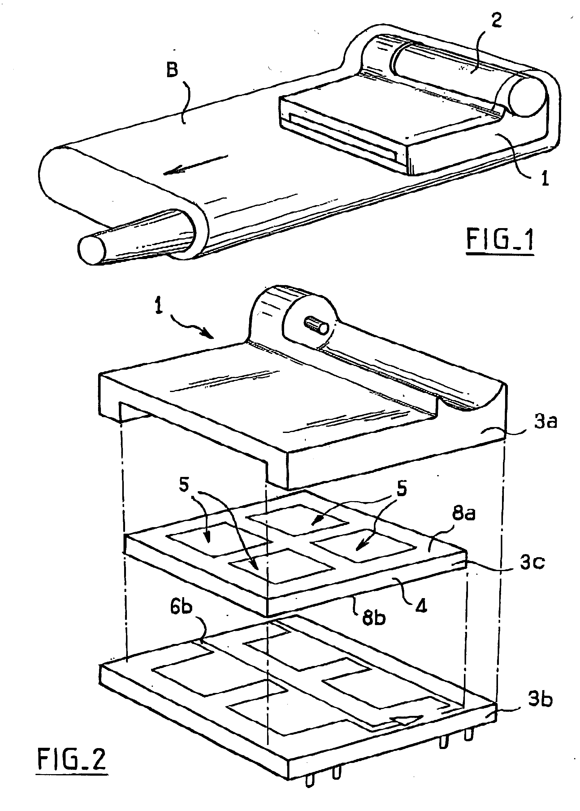
The invention relates to a miniature fuel cell powered by a hydrocarbon fuel making heavy use of micro-technologies in making and assembling the sub-assemblies of the cell. Relative to the prior art, the main innovation consists in using a semiconductor oxidised and made porous in predetermined areas, to receive an electrolytic polymer allowing the composition of the proton exchange membrane necessary for the fuel cell to operate.

Description

[0001] The present intervention relates to the field of microfuel cells for use particularly in portable electronic devices, automobile equipment and telecommunications devices.[0002] Miniaturisation of numerous devices, such as mobile phones, computers, personal digital assistants, digital cameras, etc, provokes the need for energy sources of small dimensions and high capacity.[0003] The current solution is the use of batteries. However, the life span of batteries is short, and the need for a recharge of the battery is cumbersome. Indeed, an electrical plug is sometimes hard to find, it is hard to use the portable device during the charging. Furthermore, the batteries are hard to recycle and are an environmental hazard. Plus, the batteries are expensive to make.[0004] Some intents of using fuel cells have been made.[0005] Fuel cells convert the chemical energy stored in a fuel into electrical energy by an electrochemical process which consists in causing a gas or a liquid to react ...

Claims


Application Information

Patent Timeline
IPC IPC(8): H01M8/02H01M8/04H01M8/10
CPCH01M8/1011H01M8/1023H01M8/1025H01M8/1027H01M8/1032H01M8/1037H01M8/1039H01M8/1044H01M8/106H01M8/1062H01M8/1067H01M8/1072H01M8/1074H01M8/1097Y02E60/523Y02E60/50Y02P70/50
Inventor CURLIER, PATRICKBERGAMASCO, JEAN-LUEPICHONAT, TRISTANMARECHAL, MANUELGAUTHIER-MANUEL, BERNARDSANCHEZ, JEAN-YVES
Owner SAGEM SA
Learn More