
Illuminant semiconductor element and method for mfg. same

A technology for light-emitting elements and semiconductors, which is applied in semiconductor devices, semiconductor lasers, electrical components, etc., and can solve problems such as the increase in the price of the substrate and the increase in the series resistance of the chip.

Inactive Publication Date: 2002-05-01
KK TOSHIBA
View PDF0 Cites 16 Cited by
  • Summary
  • Abstract
  • Description
  • Claims
  • Application Information

AI Technical Summary

Problems solved by technology

However, the use of a low-concentration and stable p-type GaP substrate will not only lead to an increase in the series resistance of the chip, but will also become a factor that increases the price of the substrate

Method used


Image

  • Illuminant semiconductor element and method for mfg. same
  • Illuminant semiconductor element and method for mfg. same
  • Illuminant semiconductor element and method for mfg. same

Examples


Embodiment Construction

[0035] Hereinafter, details of the present invention will be described using illustrated embodiments.

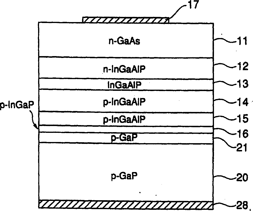
[0036] figure 1 The cross-sectional view of is showing the element configuration of the bonding type LED of one embodiment of the present invention.

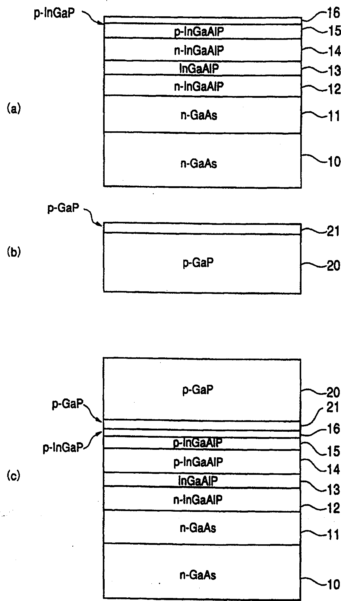
[0037] On the p-type GaP substrate 20, a high-concentration p-type GaP buffer layer 21 is formed, on which the p-type InGaP bonding layer 16, the Zn diffusion prevention layer 15 made of p-type InGaAlP, and the p-type InGaAlP are directly bonded. A cladding layer 14, an InGaAlP active layer 13, an n-type InGaAlP cladding layer 12, and an n-type GaAs current diffusion layer 11 are laminated. Then, on the lower surface of GaP substrate 20 , p-side electrode 28 is formed, and on the upper surface of current diffusion layer 11 , n-side electrode 17 is formed.

[0038] In addition, a double heterostructure structure portion contributing to light emission is also formed in each of the layers 12 , 13 , and 14 described above. In ...


PUM


Abstract

The subject of the present invention is to provide a method to prevent the diffusion of P-type dopants from the substrate to the active layer, inhibit the formation of non-light-emitting centers, so as to obtain higher brightness and stability. The semiconductor light-emitting element utilizing the chip bonding technology comprises: a double hetero structure formed of InGaAlP material layers including an active layer 13 acting as a light emitting layer and an n-type, p-type cladding layer 12, 14 having the active layer sandwiched in between, and a p-type GaP substrate 20 directly bonded to the p-type cladding layer 14 of the double hetero structure, and a Zn diffusion preventing layer formed of InGaAlP, which is interposed between the p-type cladding layer 14 and p-type GaP substrate 20. The Zn diffusion preventing layer 15 is formed by doping p-type dopant Zn and Si with n-type dopants simultaneously. When the impurity concentration of Zn, Si is Na, Nd respectively, they satisfy the condition: Na > Nd, and Nd > 2x10<17> cm-3.

Description

technical field [0001] The invention relates to a semiconductor light-emitting element using wafer direct bonding technology and a manufacturing method thereof. Background technique [0002] In recent years, various proposals have been made for light-emitting elements in the visible light region using InGaAlP-based materials. Image 6 is an element configuration diagram showing an example of a conventional InGaAlP visible light LED. On the n-type GaAs substrate 50, an InGaAlP system double-heterostructure structure part with n-type and p-type cladding layers 52, 54 sandwiching the active layer 58 is formed, and a p Side electrode 57 and n-side electrode 58 are provided on the lower surface of n-type GaAs substrate 50 . [0003] In order to adjust the emission wavelength and confine the carriers, to form the layers 52 to 54 of the double heterostructure structure, the energy band gap must be selected according to the design. Furthermore, for good epitaxial growth, it is des...

Claims


Application Information

Patent Timeline
Patent Type & Authority Applications(China)
IPC IPC(8): H01L33/30
CPCH01L33/305
Inventor 赤池康彦古川和由
Owner KK TOSHIBA
Learn More