Buffer circuit, and power conversion device using same

A power converter and snubber circuit technology, applied in the direction of converting AC power input to DC power output, converting DC power input to DC power output, high-efficiency power electronic conversion, etc., can solve problems such as high power loss, and achieve voltage transient suppression Change and reduce the effect of power loss

Inactive Publication Date: 2002-05-15
ORMON CORP
View PDF0 Cites 22 Cited by
  • Summary
  • Abstract
  • Description
  • Claims
  • Application Information

AI Technical Summary

Problems solved by technology

[0006] However, suppressing voltage transients with conventional snubber

Method used


Image

  • Buffer circuit, and power conversion device using same
  • Buffer circuit, and power conversion device using same
  • Buffer circuit, and power conversion device using same

Examples


Embodiment Construction

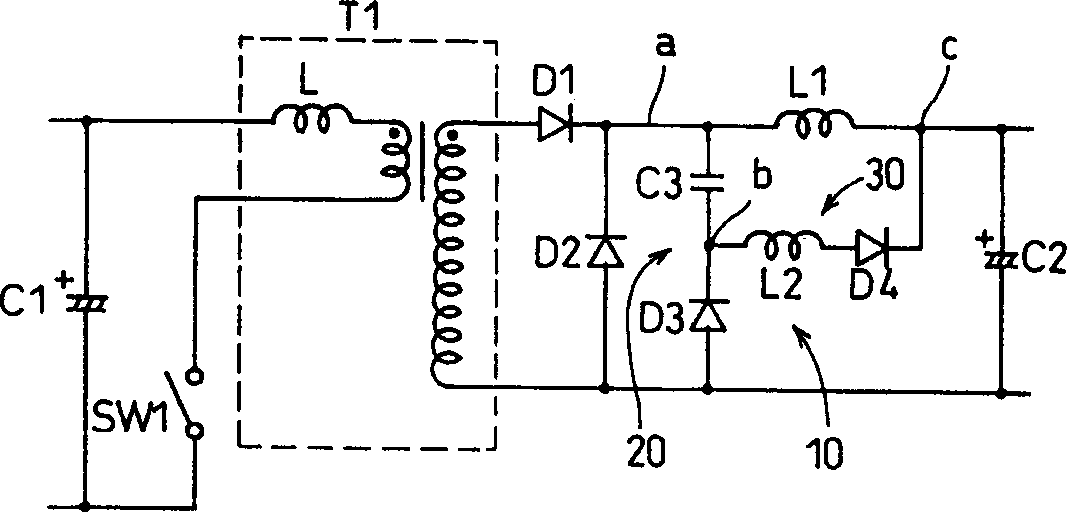
[0089] Refer below Figure 1 to Figure 1 0 illustrates the switching power supply of the snubber circuit according to the preferred embodiment of the present invention. The switching power supply is a forward scheme as an example of a power converter.

[0090] see figure 1 , the smoothing capacitor C1 on the primary side filters the full-wave rectified voltage applied to it. The converter transformer T1 includes a primary coil and a secondary coil, while the leakage inductance in the converter transformer T1 is denoted by L. The switching element SW1 is composed of a transistor, is connected in series with the primary coil of the converter transformer T1, and performs power control by turning on and off.

[0091] The anode of the rectifier diode D1 is connected to one end of the secondary coil of the converter transformer T1. The choke coil L1 and the cathode of the rectifier diode D1 are connected in series. In other words, the choke coil L1 is indirectly connected to th...


PUM


Abstract

The invention has a first series circuit consisting of a capacitor and a diode and a second series circuit consisting of a coil and a diode, the first series circuit is connected in parallel to the commutating diode in a state that the capacitor is connected to a choke coil side in the commutating diode, and the second series circuit is connected between a connecting portion of the capacitor and the diode in the first series circuit and a commutating diode non-connecting side in the choke coil.

Description

technical field [0001] The present invention relates to a snubber circuit for suppressing voltage ringing when a switching element is turned off, and a power converter, such as a switching power supply, using the snubber circuit. Background technique [0002] Examples of the power converter include an isolated switching power supply using a converter transformer and a non-isolated switching power supply not using a converter transformer. [0003] In both types of switching power supplies, the switching element is subjected to a sudden voltage change (voltage transient) when it is turned off due to the leakage inductance of the choke coil or the primary winding of the converter transformer. [0004] Snubber circuits are provided primarily to suppress voltage transients. [0005] If the switching power supply has a large leakage inductance in the primary winding of the converter transformer, the voltage transient when the switching element is turned o...

Claims


Application Information

Patent Timeline
IPC IPC(8): H02M1/34H02M3/335
CPCH02M3/33538H02M1/34H02M2001/346Y02B70/1491Y02B70/10H02M1/346H02M3/28
Inventor 坪田康弘小堀秀树丸茂克也
Owner ORMON CORP
Why Eureka
Try Eureka