Angular-rate sensor
An angular velocity sensor, velocity technology, applied in instruments, velocity/acceleration/shock measurement, navigation through velocity/acceleration measurement, etc., can solve the problem of not having
- Summary
- Abstract
- Description
- Claims
- Application Information
AI Technical Summary
Problems solved by technology
Method used
Image

Examples
Embodiment 1
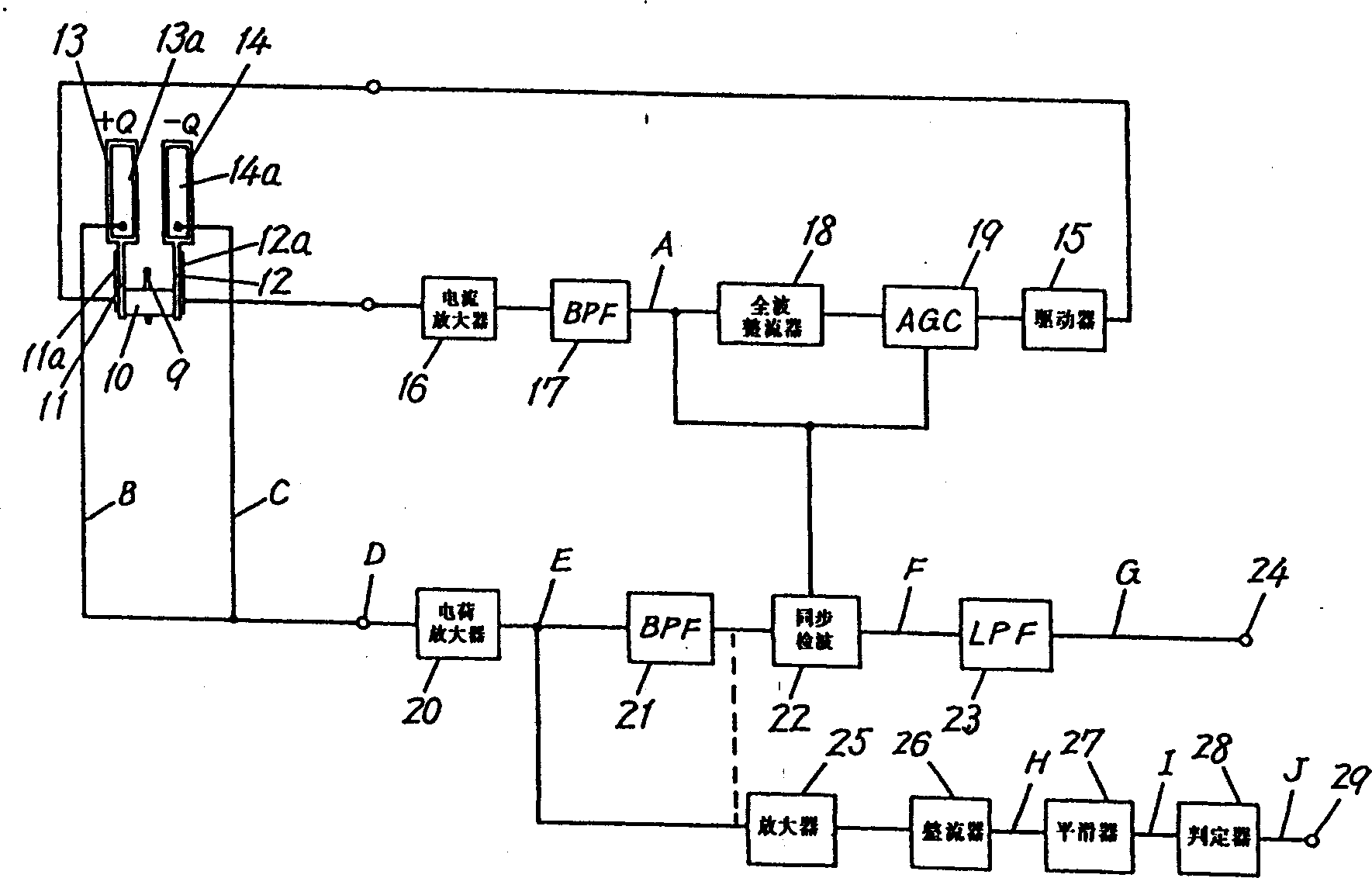
[0014] figure 1 It is a circuit diagram of the control circuit in the first embodiment of the angular velocity sensor of the present invention. The driver 15 applies a 1VP-P (peak-to-peak), 1.5KHz AC signal as a driving signal to the piezoelectric element 11a of the driving board 11 as a sensing element. As a result, the drive plates 11 and 12 begin to vibrate as a tuning fork centered on the support rod 9 in the inner and outer directions. The piezoelectric element 12a of the driving board 12 generates an induced voltage proportional to the applied signal due to the vibration of the tuning fork, and the voltage passes through the current amplifier 16 and the band-pass filter 17 to form at point A figure 2 The monitoring signal shown in A. The signal is fed back to the driver 15 through the subsequent full-wave rectifier 18 and AGC circuit 19 to perform AGC control on the driving signal. In the detection section, when the piezoelectric elements 13a and 14a detect the angu...
Embodiment 2
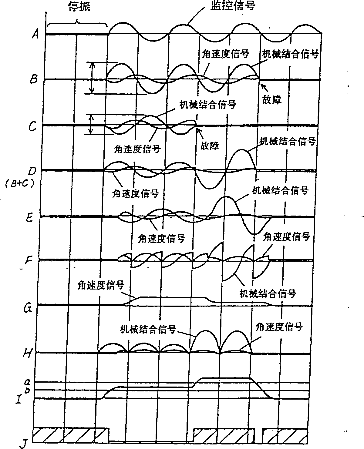
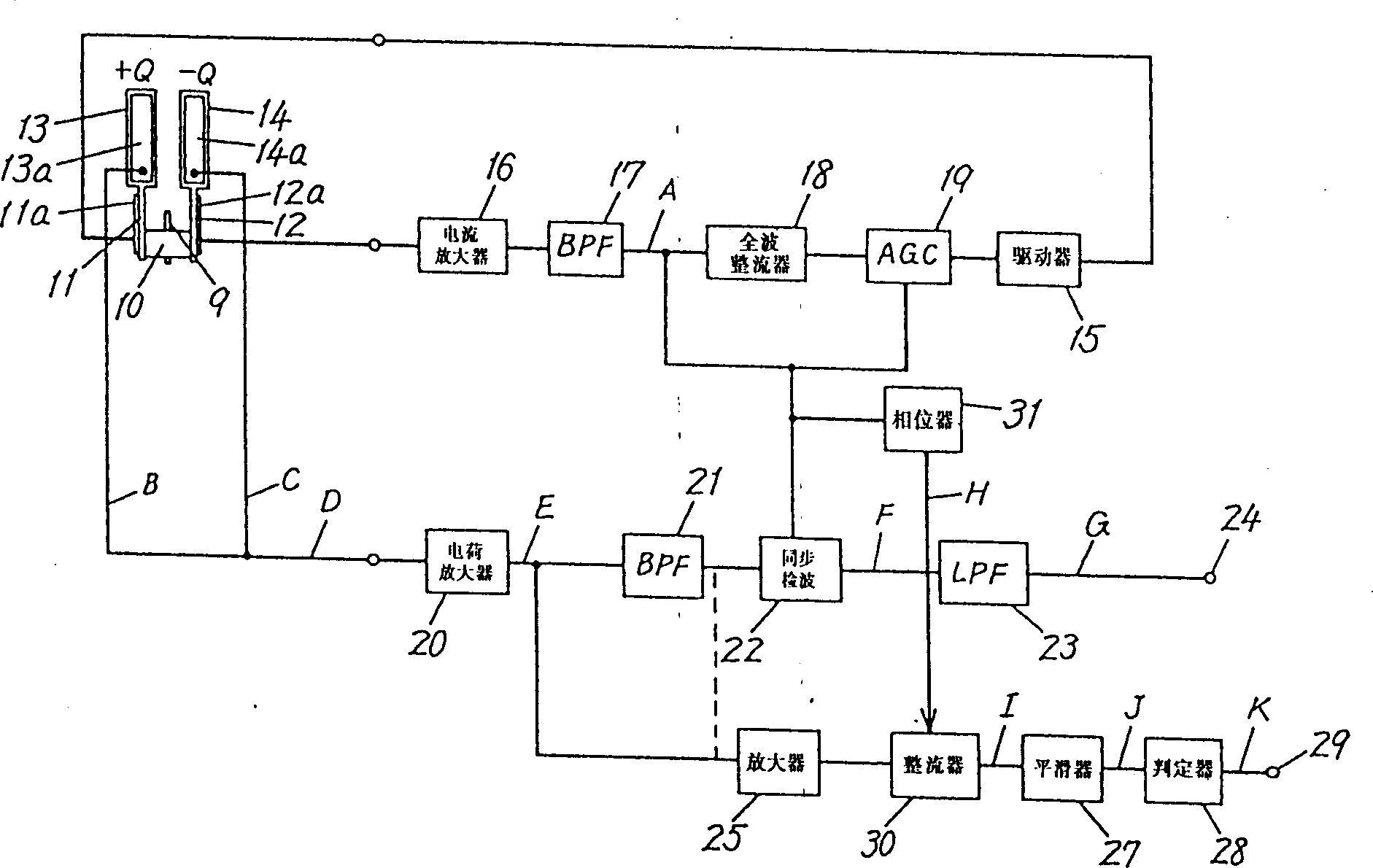
[0017] image 3 represents another embodiment, in which synchronous detector 30 is interposed between amplifier 25 and smoother 27, and uses the feedback signal of the feedback circuit in the drive signal, that is, from image 3 The signal at point A passing through the phaser 31 is subjected to synchronous detection. That is, since the angular velocity signal is also mixed in the mechanical coupling signal flowing into the amplifier 25, the angular velocity signal is canceled to bring the level of the mechanical coupling signal close to the correct value. For this purpose, as described above, phaser 31 is used to pair the incoming image 3 in point A Figure 4 The phase shift of medium signal A lags behind 90°, if using Figure 4 Shown in H has the output of the amplifier 25 from the synchronous detection of the signal with this 90° lagging phase, then as Figure 4 As shown in I, the angular velocity signal is eliminated, and the level of the mechanically combined signal ...
Embodiment 3
[0019] Figure 5 represents yet another embodiment in which the Figure 5 The middle point D is initially set to zero when adding the mechanical coupling signals obtained from the piezoelectric elements 13a and 14a. That is, in this example, for figure 1 , image 3 In the state where the sum is not zero, the balance of the detection board 13 or 14 is adjusted so that the sum of the mechanical combination signals generated by the piezoelectric elements 13a and 14a is initially set to zero. This situation is expressed in Figure 6 In D, the mechanical coupling signal does not appear in the normal state before a fault such as damage to the detection board 14 or a lead wire falling off occurs, for example. Figure 5 On point D. However, after this failure occurs, since the piezoelectric element 14a does not generate a mechanical coupling signal, as Figure 6 As shown in D, a mechanobinding signal appears. As a result, such as Figure 6 As shown in J, when a fault occurs, th...
PUM
 Abstract
Description
Claims
Application Information
 - R&D
- Intellectual Property
- Life Sciences
- Materials
- Tech Scout
- Unparalleled Data Quality
- Higher Quality Content
- 60% Fewer Hallucinations
Browse by: Latest US Patents, China's latest patents, Technical Efficacy Thesaurus, Application Domain, Technology Topic, Popular Technical Reports.
© 2025 PatSnap. All rights reserved.Legal|Privacy policy|Modern Slavery Act Transparency Statement|Sitemap|About US| Contact US: help@patsnap.com