Electric discharge machine and method of electric discharge machining

A processing device and processing method technology, applied in the direction of electric processing equipment, selection device, metal processing equipment, etc., can solve problems such as difficulties, achieve the effects of improving processing accuracy, increasing processing speed, and shortening jumping action time

Inactive Publication Date: 2002-06-26
MITSUBISHI ELECTRIC CORP
View PDF0 Cites 6 Cited by
  • Summary
  • Abstract
  • Description
  • Claims
  • Application Information

AI Technical Summary

Problems solved by technology

However, it is very difficult for the user of the electric discharge machining device to adjust these set frequencies and allowable maximum component values ​​to the optimum state.

Method used


Image

  • Electric discharge machine and method of electric discharge machining
  • Electric discharge machine and method of electric discharge machining
  • Electric discharge machine and method of electric discharge machining

Examples


Embodiment 6

[0121] Embodiment 6 of the present invention will be described below. In the above-mentioned Embodiments 4 and 5, a command trajectory is generated by the jump generation unit 1, which suppresses the frequency component values ​​in each frequency range to a predetermined value C or less. In this embodiment 6, a filter 15 is provided at the output stage of the jump control part 2, which is used to convert the resonance frequency f c Frequency component values ​​in the above frequency range are suppressed to a predetermined value C or less.

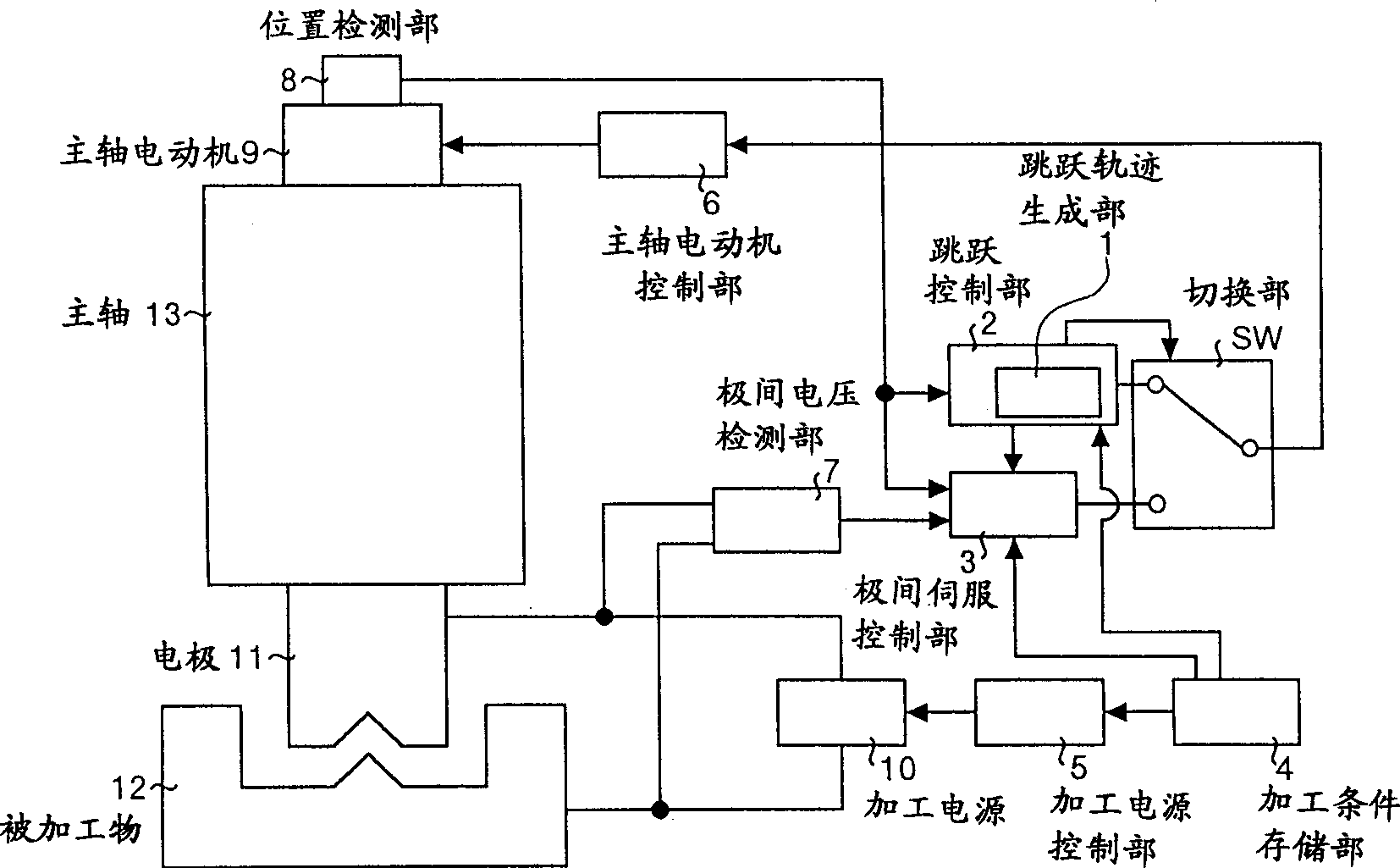
[0122] Figure 8 It is a block diagram showing the configuration of an electrical discharge machining apparatus according to an eighth embodiment of the present invention. exist Figure 8 Among them, the filter 15 is an analog filter, and the resonant frequency f c The frequency component values ​​in the above frequency range are suppressed to a predetermined value C or less and output. Other composition and figure 1 The configuration...


PUM


Abstract

An electric discharge machine is provided with a gap servo control unit for controlling the gap distance between an electrode and a workpiece while applying a prescribed voltage between the electrode and the workpiece, and a jump control unit for controlling a jump that allows the gap distance to be large temporally for a prescribed time or correspondingly to the machined state. The jump control unit is provided with a jump locus generating section for generating a smooth command locus having a frequency component within a prescribed frequency region not greater than the prescribed frequency or less than the prescribed frequency. The jump control unit controls a jump by using the smooth command locus generated by the jump locus generating section.

Description

technical field [0001] The invention relates to an electric discharge machining device and an electric discharge machining method which apply a voltage between an electrode and a processed object, and use the discharge phenomenon generated between the two electrodes to process the processed object, especially the electric discharge machining method. An electrical discharge machining device and an electrical discharge machining method that perform a jumping operation that temporarily increases the distance between poles every time a certain period of time passes or controls the jumping operation according to the processing state. Background technique [0002] In the past, the electric discharge machining device performed a jumping action after a certain period of time (that is, temporarily increasing the distance between the electrode and the workpiece), or performed a jumping action according to the processing state, and eliminated the accumulation on the electrode and the ma...

Claims


Application Information

Patent Timeline
Patent Type & Authority Applications(China)
IPC IPC(8): H04M3/53H04M3/533H04M3/537H04M11/02H04Q3/62
CPCH04M11/022H04M3/537H04M3/533H04Q3/625H04M3/5307
Inventor 中川孝幸今井祥人
Owner MITSUBISHI ELECTRIC CORP
Why Eureka
Try Eureka