Engine with rolling screw
A rolling screw and engine technology, applied in the direction of machines/engines, mechanical equipment, etc., can solve problems such as sealing and material problems that cannot be solved
- Summary
- Abstract
- Description
- Claims
- Application Information
AI Technical Summary
Problems solved by technology
Method used
Image
Examples
Embodiment Construction
[0017] The specific embodiments of the present invention will be further described below with reference to the accompanying drawings.
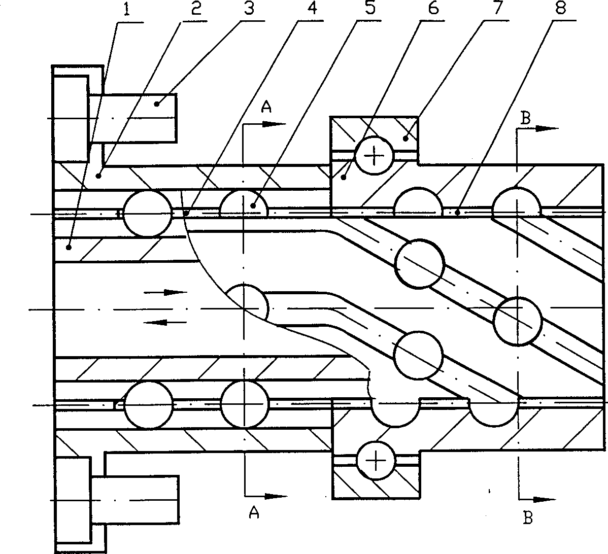
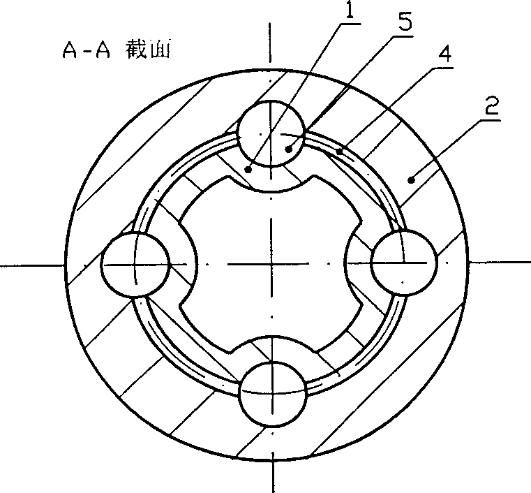
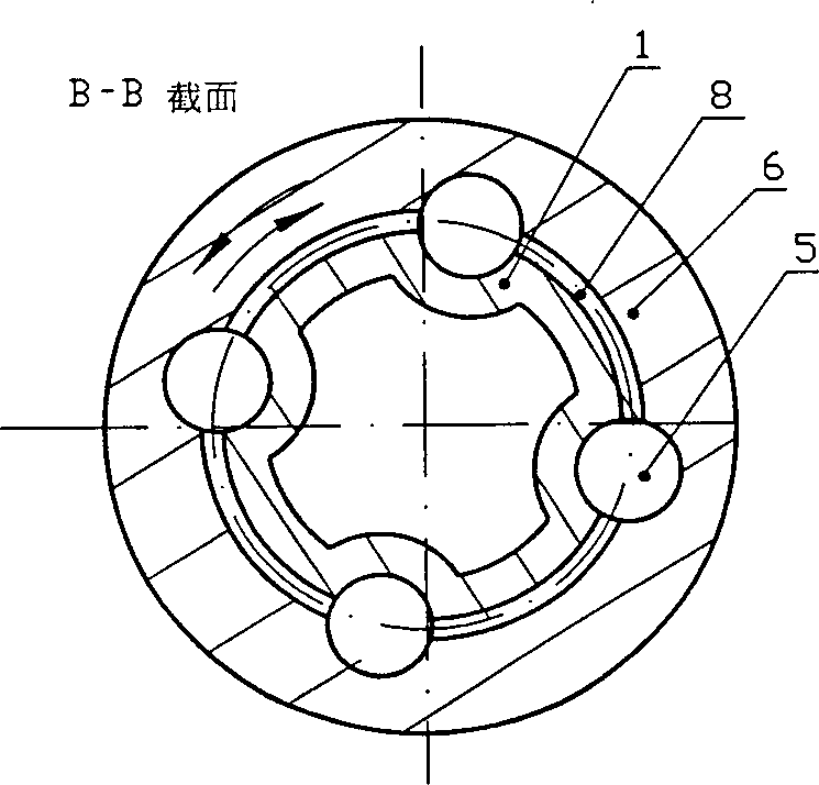
[0018] figure 1 In order to convert linear motion into rotary motion, it is composed of rolling spline pair and rolling screw pair arranged in series; rolling spline pair is composed of outer sleeve 2, middle sleeve 4, inner sleeve 1, and steel ball 5. The purpose is to limit the inner sleeve 1 to move axially; the rolling screw pair is composed of a spiral sleeve 6, a middle sleeve 8, an inner sleeve 1, and a steel ball 5. Its function is to drive the spiral sleeve when the inner sleeve 1 moves axially. 6 Turn. Straight grooves and spiral grooves are distributed on the inner sleeve 1 . The outer sleeve 2 of the rolling spline pair is fastened on the cylinder block through the outer cylinder, flange and screw 3; the thrust bearing 7 restricts the screw sleeve 6 from moving axially but can only rotate; sports. Thus, when the piston (see I...
PUM
 Abstract
Description
Claims
Application Information
 - R&D
- Intellectual Property
- Life Sciences
- Materials
- Tech Scout
- Unparalleled Data Quality
- Higher Quality Content
- 60% Fewer Hallucinations
Browse by: Latest US Patents, China's latest patents, Technical Efficacy Thesaurus, Application Domain, Technology Topic, Popular Technical Reports.
© 2025 PatSnap. All rights reserved.Legal|Privacy policy|Modern Slavery Act Transparency Statement|Sitemap|About US| Contact US: help@patsnap.com


