
Rotary compressor

A technology of rotary compressor and compressor, applied in the direction of rotary piston machinery, rotary piston pump, mechanical equipment, etc., can solve the problems of destroying ozone and destroying the ozone layer.

Inactive Publication Date: 2002-09-25
SANYO ELECTRIC CO LTD
View PDF3 Cites 5 Cited by
  • Summary
  • Abstract
  • Description
  • Claims
  • Application Information

AI Technical Summary

Problems solved by technology

This kind of R12 and R22 has the potential to destroy the ozone. When it is discharged into the atmosphere and reaches the ozone layer above the earth, there will be a problem of destroying the ozone layer, so Freon becomes the object of restricted use.

Method used


Image

  • Rotary compressor
  • Rotary compressor
  • Rotary compressor

Examples


Embodiment Construction

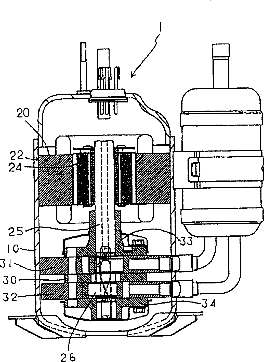
[0055] Figure 6 Indicates the compression of a polyglycol lubricant or a poly-α-olefin as a lubricating base oil, and taking, for example, carbon dioxide as a natural cooling medium that does not contain chlorine in molecules such as an evaporative HFC-based cooling medium. The rotary compressor of the present invention for carbon dioxide, the condenser b that condenses and liquefies the cooling medium, the expansion device c that reduces the pressure of the cooling medium, and the evaporator d that evaporates the liquefied cooling medium are connected by cooling medium pipes An example of a refrigeration circuit formed together.

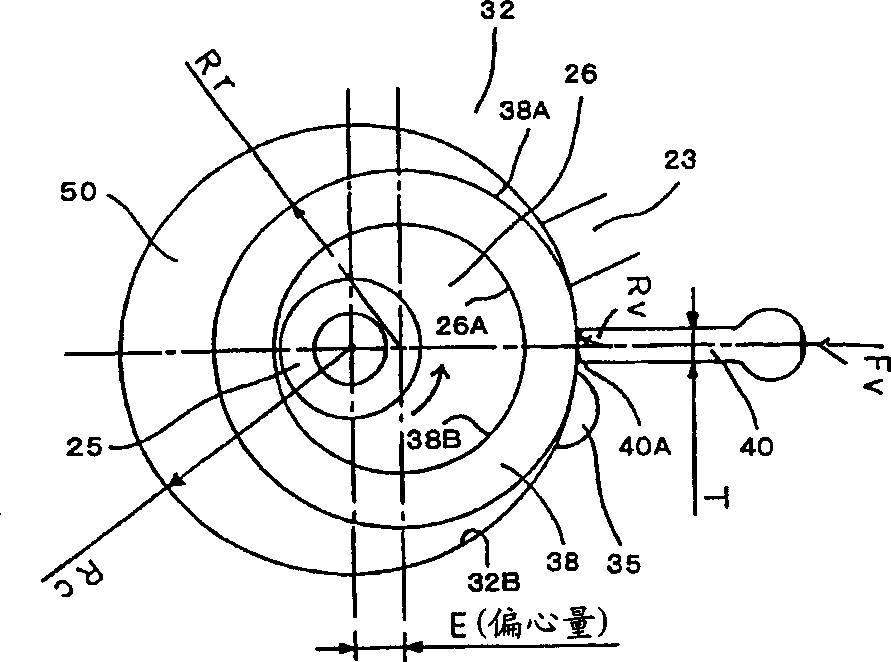
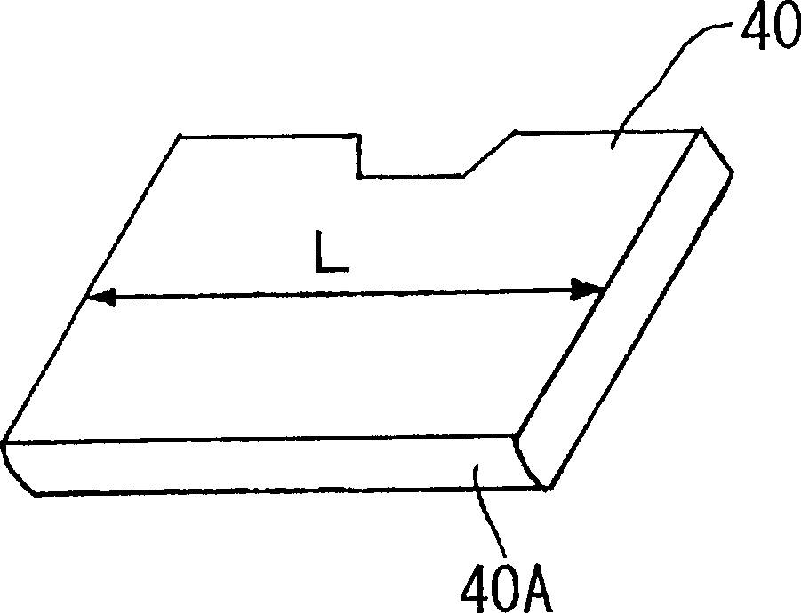
[0056] exist Figure 5 Among them, when the eccentricity (cm) between the rotation center (O1) of the rotating shaft 25 and the roller center (O2) of the roller 38 is E, the center (O3) of the curvature radius (Rv) of the connecting blade 40 and the roller center (O2 ) and the straight line (L1) of the connection center (O3) and the rotation cent...


PUM


Abstract

A rotary compressor which uses carbonic acid gas as the refrigerant, polyalkylene glycol as a lubricant, or polyalfa olefin or mineral oil as a base oil. The compressor includes a roller and a vane whose radius of curvature (Rv) (cm) at a sliding contact portion with respect to said roller can be represented by the following Expression (1): <DF NUM="Expression (1)">T < Rv < Rr < / DF> where T is the thickness (cm) of the vane, and Rr is the radius of curvature (cm) of the outer periphery of the roller which slidingly comes into contact with the vane. <IMAGE>

Description

field of invention [0001] The present invention relates to a rotary compressor using carbon dioxide as a cooling medium and polyglycol lubricant or poly-α-olefin, or mineral oil as the base oil of lubricating oil. More specifically, the present invention relates to a structure of a roller and a blade suitable for a rotary compressor which prevents abnormal wear of the roller and the blade and has improved reliability. Background technique [0002] Compressors for refrigerators, vending machines, and product showcases, as well as compressors for household and office air conditioners, mostly use dichlorodifluoromethane (R12) and chlorodifluoromethane (R22) as cooling media in the prior art. . Since the R12 and R22 have the potential to destroy the ozone, when they are discharged into the atmosphere and reach the ozone layer above the earth, there will be a problem of destroying the ozone layer, so Freon has become the object of restricted use. This ...

Claims


Application Information

Patent Timeline
IPC IPC(8): F04C29/00C10M171/00F01C21/08F04C18/356F04C23/00F04C29/02
CPCC10M171/008F01C21/08F04C18/3564F04C23/001F04C23/008F04C29/02F04C2210/1027F04C2210/1072F04C29/00
Inventor 松本兼三须永高史松浦大高桥康树
Owner SANYO ELECTRIC CO LTD
Learn More