Loudspeaker device
A loudspeaker and subtractor technology, applied in the direction of frequency/direction characteristic devices, sensors, transducer circuits, etc., can solve problems such as difficult control and large feedback, and achieve the effect of stable characteristics
- Summary
- Abstract
- Description
- Claims
- Application Information
AI Technical Summary
Problems solved by technology
Method used
Image
Examples
Embodiment 1
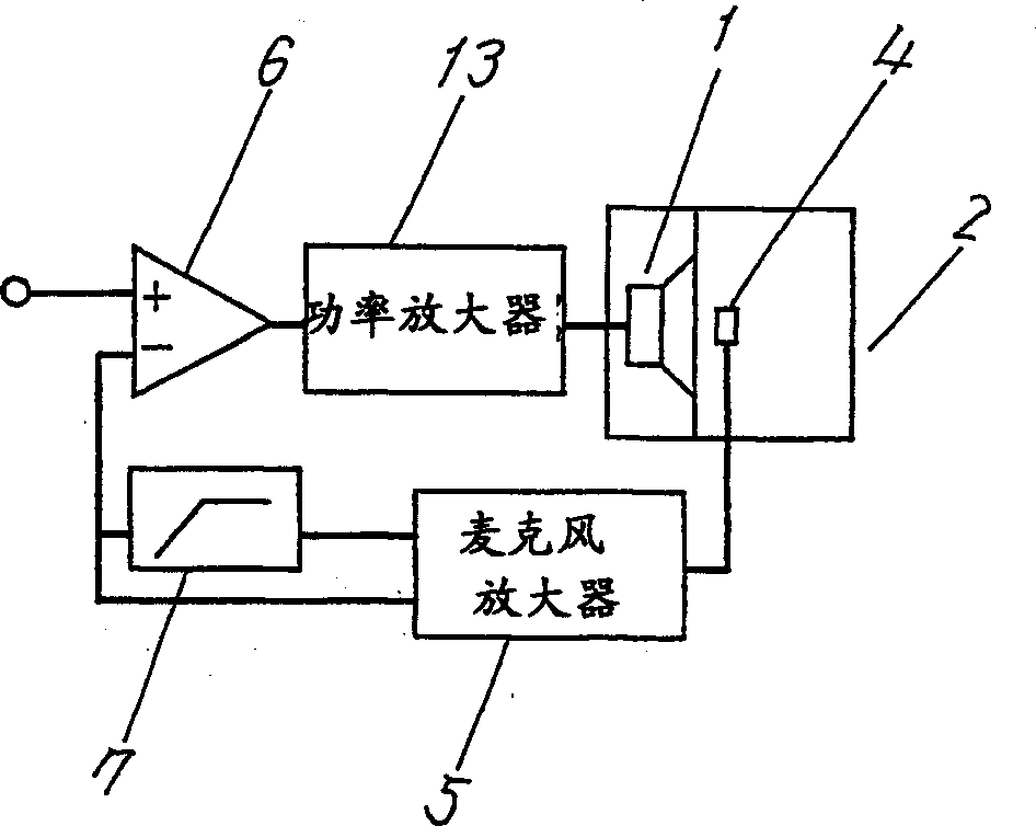
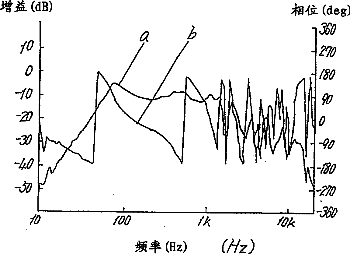
[0039] Fig. 1 is a block diagram of an acoustic circuit according to Embodiment 1 of the present invention, Fig. 2 is a characteristic diagram of an acoustic output, a is a sound pressure characteristic, and b is a phase characteristic. Next, the overall structure of the speaker device will be described with reference to FIG. 1 .
[0040] In the figure, 1 is a speaker unit, 2 is an acoustic tube coupled with the front of the speaker unit 1, 4 is a microphone installed in the acoustic tube 2, the sound wave emitted from the speaker unit 1 is detected by the microphone 4 inside the acoustic tube 2, Input to the subtractor 6 through the high-pass filter 7, at the same time, the signal detected by the microphone 4 is directly input to the subtractor 6, mixed with the signal from the outside, the input signal is corrected, amplified by the power amplifier 13, and input to the speaker Unit 1.
[0041] The relationship between the speaker unit 1 and the acoustic tube 2 is that the a...
Embodiment 2
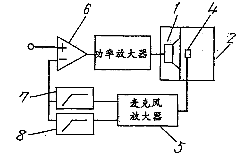
[0045] Fig. 3 is the block diagram of the acoustic circuit of other embodiment of the present invention, Fig. 4 (A) is the microphone output signal characteristic figure, Fig. 4 (B) is the sound output characteristic figure, a is the sound pressure characteristic, b is the phase characteristic. Only the difference from Embodiment 1 will be described. The acoustic output signal detected by the microphone 4 is connected to the subtractor 6 through two high-pass filters 7 and 8 connected in parallel to form a negative feedback circuit. 7 is a 2nd-order high-pass (-12dB / oct) filter, and 8 is a 1st-order high-pass (6dB / oct) filter.
[0046] FIG. 8(A) is a frequency characteristic of a conventional microphone signal, and low-frequency components are enhanced by feedback up to low frequencies. However, in this embodiment, as shown in FIG. 4 , the level of the low-frequency components is lowered, and enhancement of the low-frequency components cannot be performed.
[0047] In additio...
Embodiment 3
[0050] Fig. 5 is the block diagram of the acoustic circuit of other embodiment of the present invention, Fig. 6 (A) is the microphone output signal characteristic diagram, Fig. 6 (B) is the acoustic output characteristic diagram, a is the sound pressure characteristic, b is the phase characteristic. Only the difference from Embodiment 1 will be described. A secondary high-pass filter 7 for processing the output signal detected by the microphone 4 is connected and the output signal is connected to the subtractor 6. At the same time, the output signal of the aforementioned microphone 4 will be processed. The (-12dB / oct) or (-6dB / oct) low-pass filter 9 is connected to the subtractor 6 to form a negative feedback circuit.
[0051] By means of taking out low-frequency components by this low-pass filter 9 and performing phase compensation, a loudspeaker device with excellent acoustic characteristics can be provided. The filter 7 performs acoustic tube resonance independently, can be...
PUM
 Abstract
Description
Claims
Application Information
 - R&D
- Intellectual Property
- Life Sciences
- Materials
- Tech Scout
- Unparalleled Data Quality
- Higher Quality Content
- 60% Fewer Hallucinations
Browse by: Latest US Patents, China's latest patents, Technical Efficacy Thesaurus, Application Domain, Technology Topic, Popular Technical Reports.
© 2025 PatSnap. All rights reserved.Legal|Privacy policy|Modern Slavery Act Transparency Statement|Sitemap|About US| Contact US: help@patsnap.com


