Differential signal electrical connectors

An electrical connector, differential signal technology, applied in the direction of electrical connection of printed components, electrical components, printed circuit components, etc., can solve the problems of unequal electrical delay, deterioration of differential signal quality, etc., to achieve the effect of reducing noise and efficient wiring

Inactive Publication Date: 2002-11-06
AMPHENOL CORP
View PDF12 Cites 13 Cited by
  • Summary
  • Abstract
  • Description
  • Claims
  • Application Information

AI Technical Summary

Problems solved by technology

Due to the different signal path lengths of the current connectors (as shown in Figure 2 and image 3 shown), so the electrical delay of each path is not equal, which can deteriorate the quality of the differential signal due to induced distortion

Method used


Image

  • Differential signal electrical connectors
  • Differential signal electrical connectors
  • Differential signal electrical connectors

Examples


Embodiment Construction

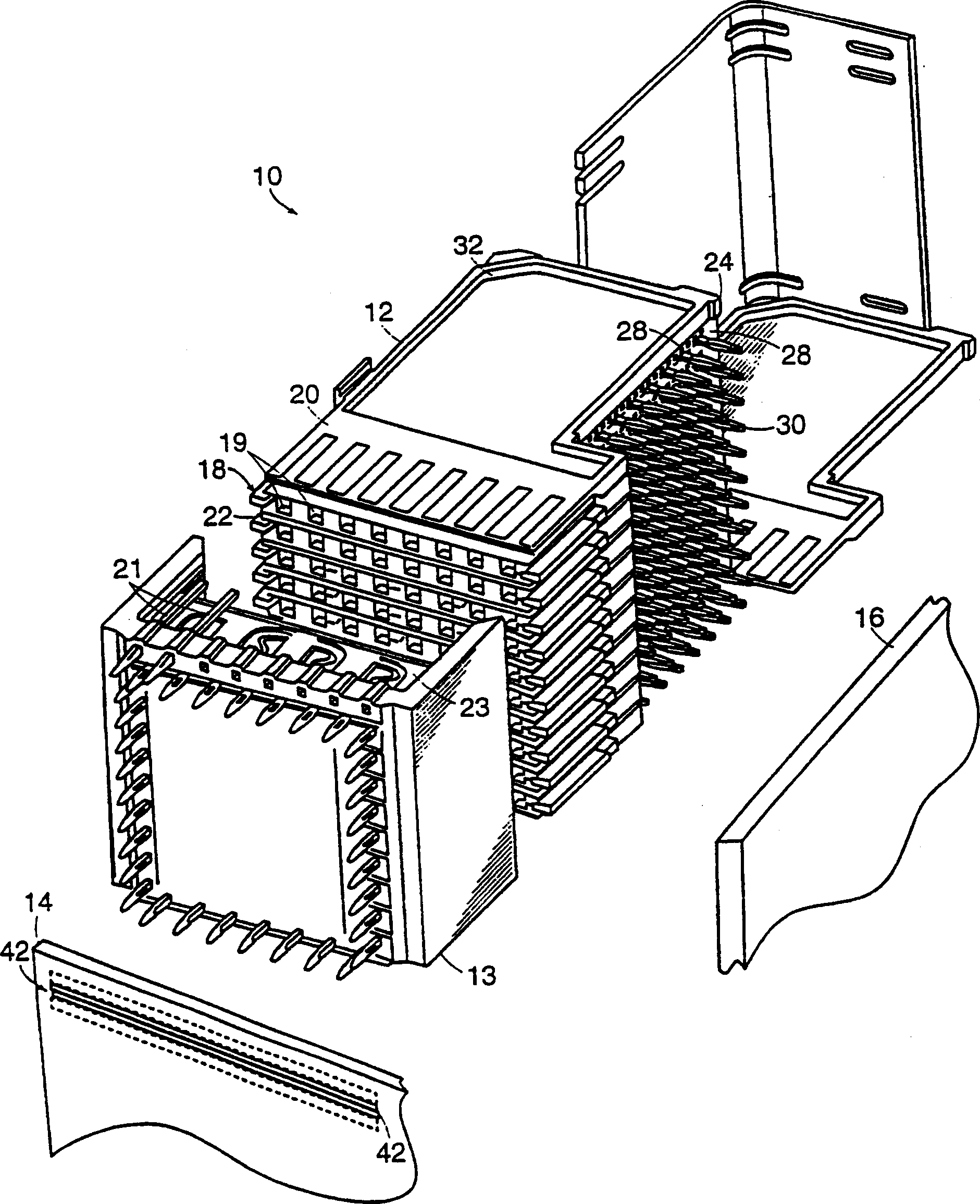
[0033] refer to figure 1 , the electrical system 10 includes a modular connector 12 that connects a backplane 14 to a daughterboard 16 . Connector 12 includes a plurality of connector modules 18 capable of connecting a set of electrical signals, whether differential, non-differential, or a combination of both types.

[0034]For example, electrical connector module 18 may conduct a differential pair of electrical signals between electrical components of system 10 (eg, motherboard 14 and daughterboard 16 ), if assembled as described below. Each connector module 18 has a set of parallel opposite sides 20 , 22 . The sides 20 , 22 each terminate along an edge 24 of the connector module 18 . (As shown, edge 24 is a flat surface. However, other configurations may be used). Extending from edge 24 is a set of connecting pins 28 . Shielding (not shown) may be placed between modules 18 .

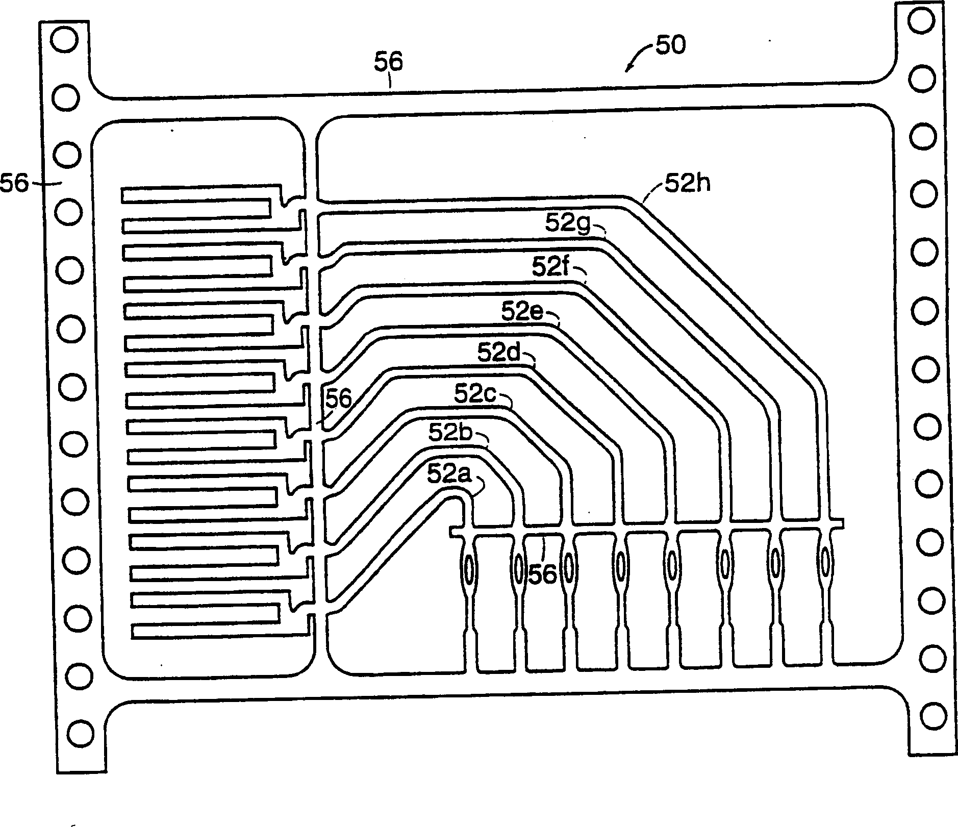
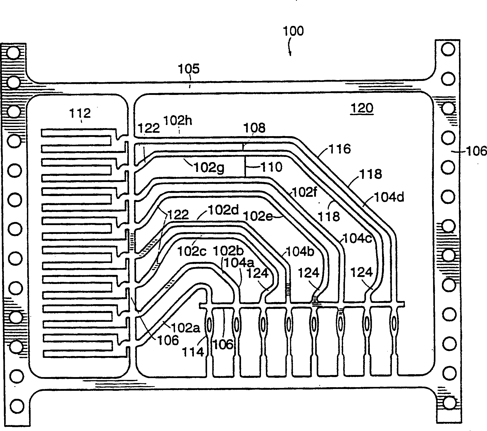
[0035] It should be noted that in a preferred embodiment, the openings 19 of each module 18 a...


PUM


Abstract

An electrical connector module for transmitting a plurality of differential signals between electrical components (14,16). The connector is composed of a plurality of modules (18) having a set of signal conductor (102) pairs (104) with a first signal path and a second signal path. Each signal path has a pair of contact segments (116) extending between the contact portions. For each pair of signal conductors, the first spacing between the transition segments is less than the second spacing between that pair of signal conductors and any other pair of signal conductors in the group. An embodiment that can improve the linearity is given.

Description

[0001] related application [0002] This application is a continuation of US Application Serial No. 08 / 797,537, filed February 7, 1997, and entitled: High Speed, High Density Electrical Connector. technical field [0003] The present invention relates to electrical connectors, and more particularly, the present invention relates to modular electrical connectors for providing signal paths for differential signals between a motherboard and a daughterboard or other electrical components. Background technique [0004] Special electrical connectors can be used to connect different components of the electrical system. Typically, such electrical connectors connect a large number of electrical signals between a series of daughter boards to the motherboard. Connect the motherboard and daughterboard at right angles. Electrical connectors are generally modular. For example, a planar, two-dimensional metal lead frame contains several signal paths, each of which is bent at right angle...

Claims


Application Information

Patent Timeline
IPC IPC(8): H01R13/648H01R12/72H01R13/646H01R13/6471H01R13/6473H01R24/00H01R24/44H05K1/02H05K1/11H05K3/04H05K3/42H05K7/06
CPCH01R12/724H01R12/727H01R13/6471H01R13/6473H01R13/6587H01R24/44H05K1/0237H05K1/115H05K1/116H05K3/429H05K2201/044H05K2201/09236H05K2201/09718H05K2201/10189H01R13/648
Inventor 托马斯·S·科恩马克·W·盖乐斯菲利普·T·斯托克
Owner AMPHENOL CORP
Why Eureka
Try Eureka