Gas turbine

A gas turbine and turbine shaft technology, applied in mechanical equipment, engine functions, engine components, etc., can solve problems such as gas turbine efficiency limitations, and achieve the effect of small pressure loss and simple discharge

Inactive Publication Date: 2002-11-20
SIEMENS AG
View PDF0 Cites 3 Cited by
  • Summary
  • Abstract
  • Description
  • Claims
  • Application Information

AI Technical Summary

Problems solved by technology

This limits the efficiency of the gas turbine

Method used


Image

  • Gas turbine
  • Gas turbine
  • Gas turbine

Examples


Embodiment Construction

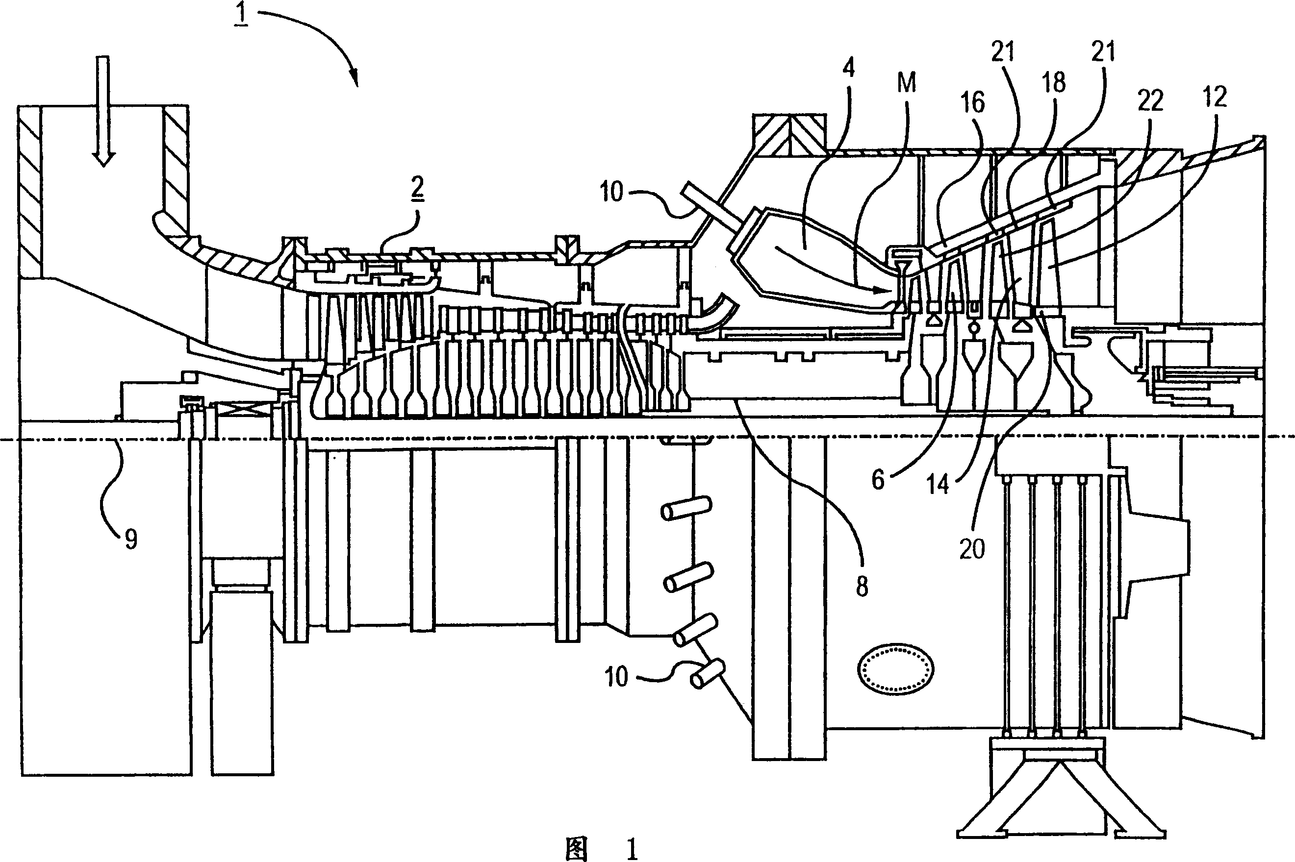
[0023] The gas turbine 1 shown in FIG. 1 has a compressor 2 for combusting air, a combustion chamber 4 and a turbine 6 for driving the compressor 2 and a generator or working machine not shown. The turbine 6 and the compressor 2 are arranged on a common turbine shaft 8 , also referred to as a turbine rotor, which is connected to a generator or a working machine and is rotatable about a central axis 9 .

[0024] The combustion chamber 4 is equipped with a number of burners 10 for burning liquid or gaseous fuels. It has thermal insulation not shown in detail on its inner wall.

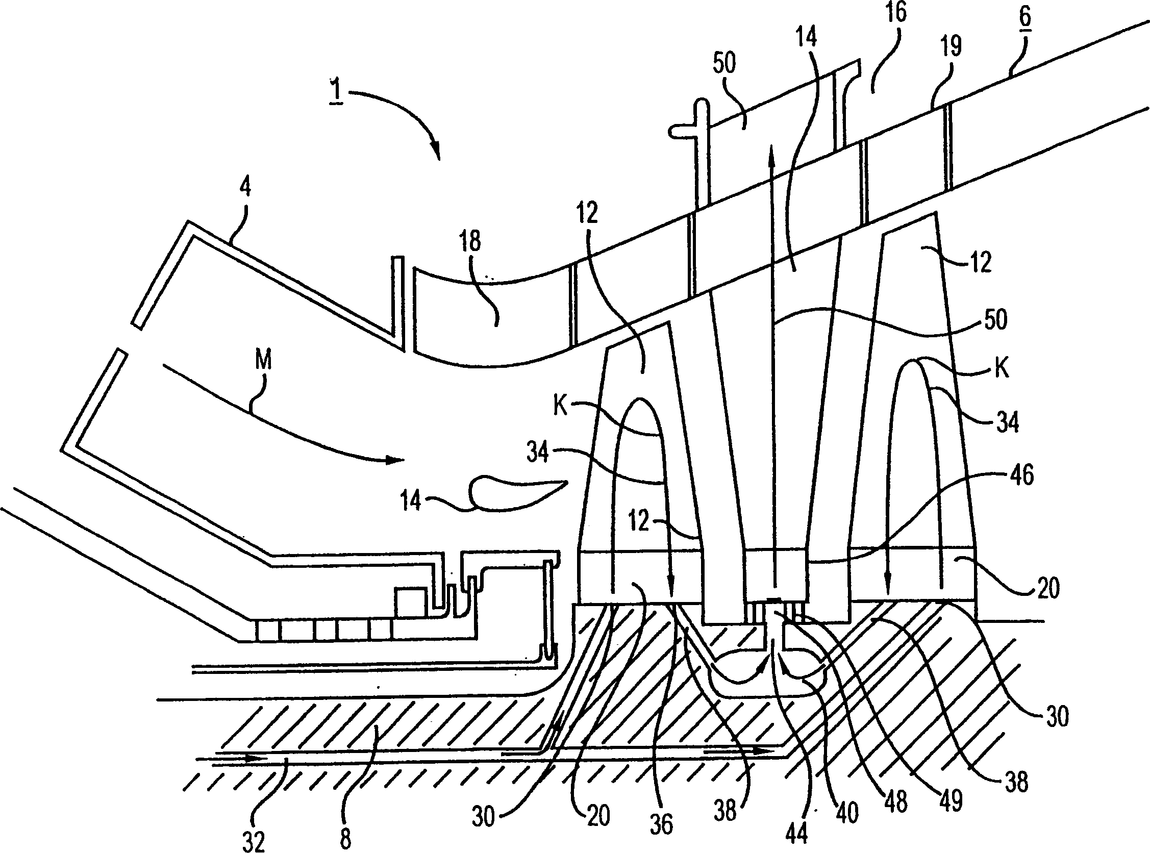
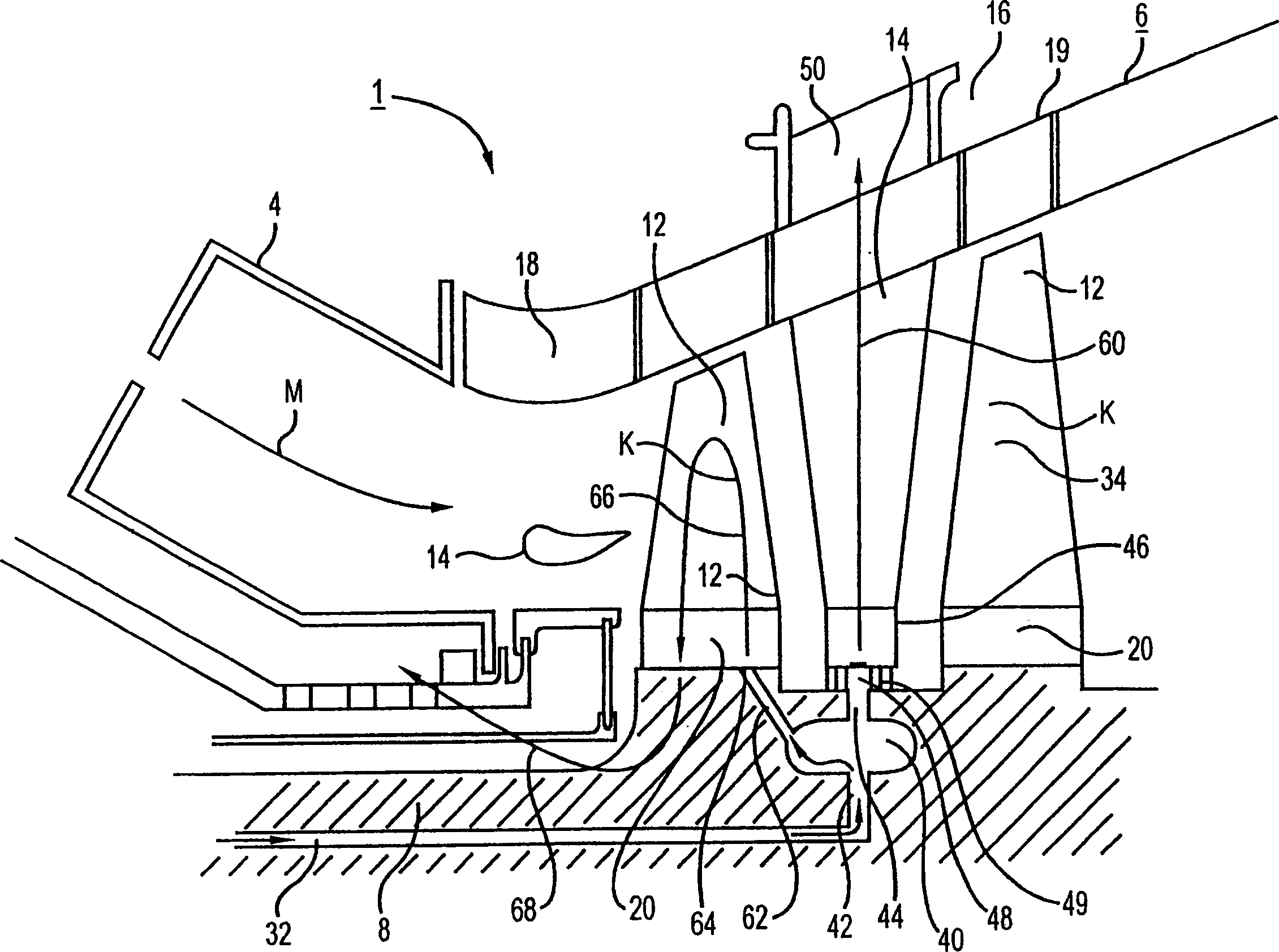
[0025] The turbine 6 has a number of rotatable rotor blades 12 connected to the turbine shaft 8 . The working blades 12 are arranged on the turbine shaft 8 in the form of blade rows, forming several working blade groups. In addition, the turbine 6 also includes a number of fixed guide vanes 14, which are also fixed on an inner casing 16 of the turbine 6 in the form of blade rows, forming a set of guide...


PUM


Abstract

In a turbine (1) with several working blades assembled on the turbine shaft (8) assembled into a working blade group and several guide blades (14) connected to the turbine casing assembled into a guide blade group, in order to Particularly high efficiency is achieved in the case of a simple and reliable cooling of the turbine blades (12), (14). According to the invention, at least some of the guide vanes (14) have a coolant inlet (48) at their free end facing the turbine shaft (8).

Description

technical field [0001] The invention relates to a gas turbine, which has a plurality of working blades arranged on a turbine shaft which are respectively assembled into a working blade group and several guide blades which are respectively assembled into a guide blade group and connected with a turbine casing. Background technique [0002] Gas turbines are used in many fields to drive electrical generators or working machines. Here, the energy contained in the fuel is used to generate the rotation of the turbine shaft. For this purpose, fuel is burned in a combustion chamber into which is also fed air compressed by a compressor. The high-temperature and high-pressure working medium formed by fuel combustion in the combustion chamber passes through a turbine unit connected behind the combustion chamber, where it expands to perform work. [0003] In order to generate the rotary motion of the turbine shaft, a number of working blades, usually assembled i...

Claims


Application Information

Patent Timeline
Patent Type & Authority Applications(China)
IPC IPC(8): F01D9/02F01D5/08F01D5/18F01D25/12F02C7/18
CPCF01D5/085F01D5/187F01D25/12F02C7/18F05D2260/232F05D2260/205
Inventor 彼得·蒂曼
Owner SIEMENS AG
Why Eureka
Try Eureka