Electric actuating device

An actuating device, electric technology, applied in the direction of electromechanical devices, transmission devices, electric components, etc., can solve the problem of high cost, achieve the effect of simplifying the structure, reducing the driving force requirements, and reducing the driving force

Inactive Publication Date: 2002-11-27
NAM CORP
View PDF0 Cites 6 Cited by
  • Summary
  • Abstract
  • Description
  • Claims
  • Application Information

AI Technical Summary

Problems solved by technology

Therefore, for the return stroke without a large load, the motor and many mechanical parts greatly exceed the design specifications, which is also the reason for the high cost of the previous electric actuator

Method used


Image

  • Electric actuating device
  • Electric actuating device
  • Electric actuating device

Examples


Embodiment Construction

[0037] Embodiments of the present invention will be described below with reference to the drawings. Here, parts that are the same as or equivalent to those in the prior art are denoted by the same symbols, and detailed description thereof will be omitted.

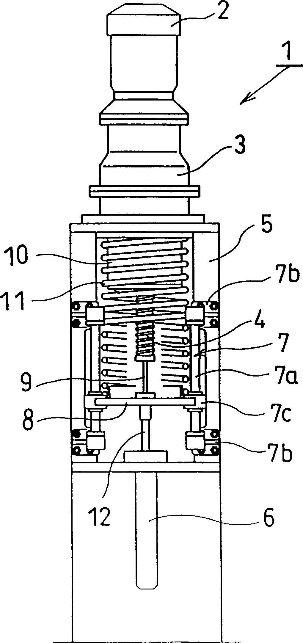
[0038] figure 1 A linear actuator 1 relating to an embodiment of the present invention is shown, which is used as a cylinder (injection cylinder) of an injection molding machine, and a driving device for a plunger pump (hereinafter referred to as a pressurization cylinder). In this linear actuator 1, as the reducer 3, a reducer such as a planetary gear reducer whose input shaft and output shaft are on the same axis is used, and the axes of the motor 2, the reducer 3, and the screw 4 are all arranged in a straight line superior. Moreover, the rotating shaft of the motor 2 and the rotating shaft of the reducer 3 are set as hollow shafts, and the screw 4 passing through the hollow shafts is moved in the axial direction (the ...


PUM


Abstract

An electric actuator is provided, which realizes frequent starting and stopping with a simple structure, low cost, and high energy efficiency. In the return stroke of the low-load operation state, the energy generated by the motor 2 and the kinetic energy generated when the movable part stops are absorbed and accumulated in the coil spring 11 . Therefore, there is no need to generate a braking force with an electric or mechanical brake or the like. In addition, there is no need for a structure to solve problems such as heat generation, and the movable part of the linear actuator 1 can be quickly stopped. On the other hand, during the operation stroke, since the coil spring 11 expands, the energy accumulated in the coil spring 11 is released as kinetic energy, thereby reducing the driving force required of the motor 2 .

Description

technical field [0001] The invention relates to an electric actuator (Actuator) suitable for high-frequency reciprocating motion. Background technique [0002] The actuating device, for example, when used as a cylinder block of an injection molding machine or a driving device for a pressurized cylinder, is required to reciprocate at a high frequency between moderate strokes, and has a relatively large force, and the actuating device is mostly The power generated by oil pressure is adopted. However, considering the energy-saving and easy-to-control requirements of the actuating device in today's market, there is an urgent need to replace it with an electric actuating device. [0003] Such electric actuators include linear actuators and rotary actuators. The linear actuator device obtains the output of linear motion by reducing the speed of the high-speed rotating motor with the gear reduction device; the rotary actuator device obtains the output of rotary motion. The linea...

Claims


Application Information

Patent Timeline
IPC IPC(8): B29C45/58B29C45/40B29C45/50B29C45/76F16H25/20F16H33/02H02K7/06
CPCB29C45/4005B29C45/5008B29C45/76B29C2045/1798F16H25/2015F16H25/2204F16H2025/2068H02K7/06B29C45/58
Inventor 山田富稔尾形文弘
Owner NAM CORP
Why Eureka
Try Eureka