Optical fiber sensor for multiparameter non-contact defocusing detection of product surface

A fiber optic sensor and defocus detection technology, which is applied in the field of precision measurement, can solve problems such as complex structure of the measurement system, many components used, and difficult detection problems, and achieve high measurement accuracy, good safety, and strong practicability.

Inactive Publication Date: 2002-12-11
TSINGHUA UNIV
View PDF0 Cites 13 Cited by
  • Summary
  • Abstract
  • Description
  • Claims
  • Application Information

AI Technical Summary

Problems solved by technology

[0003] Judging from the current progress in this field, general sensors serve special instruments or devices for a single measured parameter, and can only realize the measurement of a single parameter of a certain type of product. Although scholars at home and abroad, such as[ S.H.Wang, C.J.Jin, C.J.Tay, C.Quan, H.M.Shang, "Design of an optical probe for testing surface roughness and micro-displacement," Precision Engineering, 25258-265 (2001)] proposed a two-parameter product quality measurement method, However, it is still unable to meet the requirements for multi-parameter detection and comprehensive evaluation of products with complex structures and high-precision requirements; it is also difficult to integrate the three-dimensional coordinate detection of products and the detection of microscopic appearance, and there are still the following Technical problems and deficiencies: ①The change of the reflectivity of the measured surface will affect the performance of the optical detection method; ②The structure of the measurement system is complex, and there are many components used, which are difficult to adjust; ③The inclination of the measured surface will affect the detection results of the size and height;④ Due to the limitation of the structure size of the probe, it is only suitable for the detection of flat surfaces or the outer surface of the product, but it is difficult to solve the detection problem of the inner surface of the product, especially the product with a relatively small complex inner surface.

Method used


Image

  • Optical fiber sensor for multiparameter non-contact defocusing detection of product surface
  • Optical fiber sensor for multiparameter non-contact defocusing detection of product surface
  • Optical fiber sensor for multiparameter non-contact defocusing detection of product surface

Examples


Embodiment Construction

[0021] The specific structure, measurement principle and preferred mode of the multi-parameter non-contact defocus detection optical fiber sensor proposed by the present invention will be described in detail below in conjunction with the accompanying drawings:

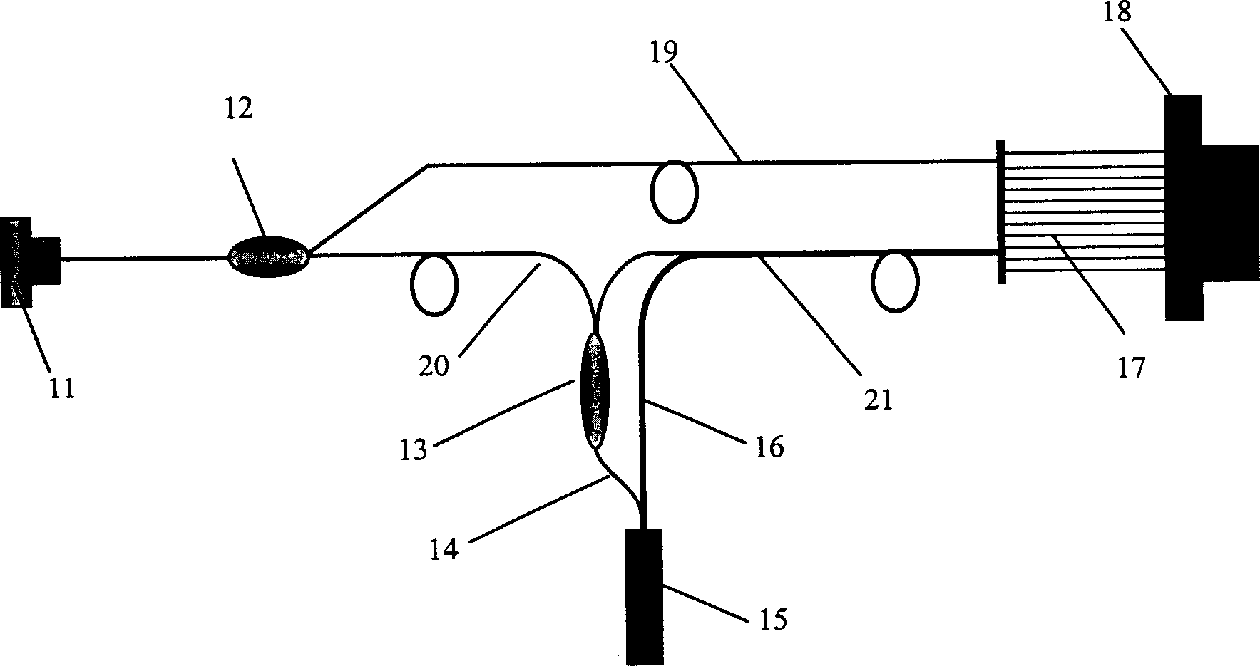
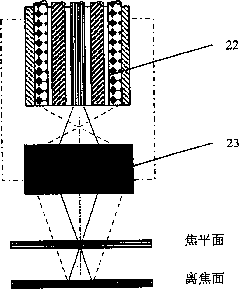
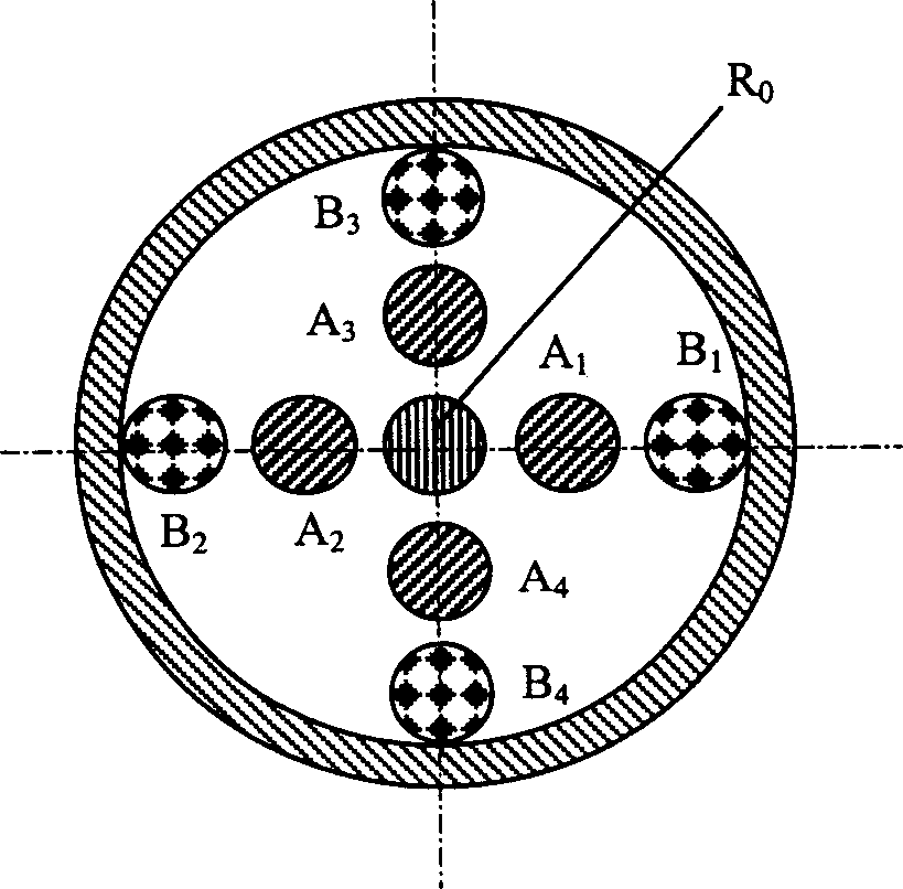
[0022] figure 1 It is a schematic structural diagram of the embodiment of the present invention. It mainly includes a light source 11 , a fiber optic splitter 12 , a Y-type fiber coupler 13 , a sensor probe 15 , a reference fiber 19 , a receiving fiber array 17 and a photoelectric receiver 18 . Sensor probe 15 is made up of optical fiber transmission light beam 22 and microscopic objective lens 23, and microscopic objective lens adopts optical fiber self-focusing lens, is solidified on the lower end face of optical fiber transmission light beam with certain distance; Optical fiber transmission light beam 22 is made up of nine optical fibers (as figure 2 shown); the nine optical fibers are distributed symmetrically at...


PUM


Abstract

The optical fiber sensor consists of laser light source, Y-type fiber coupler, sensor probe comprising light transmitting fiber bundle and microscopic objective, reference fiber and receiving fiber array and photoelectronic receiver. Its high transmitting fiber bundle consists of nine fibers in a spoke array mode; the Y-type fiber coupler is connected to the central fiber as the common emitting and receiving light channel and the other eight receiving and reference fibers are connected with photoelectronic receiver via receiving fiber array. By means of special signal extraction, roughness, size, shape and information may be measured separately without contact and without beint affected by the fluctuation in the light source and the reflectivity change of the measured surface.

Description

technical field [0001] The invention relates to an optical fiber sensor, in particular to an optical fiber sensor for multi-parameter non-contact detection on the surface of a product, belonging to the technical field of precision measurement. Background technique [0002] The detection of product quality includes the detection of size and surface topography. The former includes the detection of length dimensions and form and position dimensions such as flatness, cylindricity, and verticality; while the latter can be divided into surface microscopic shapes. The detection of appearance (such as roughness) and macroscopic topography (that is, shape). In recent years, new technologies and methods for product size and shape inspection have emerged continuously. Due to the inherent advantages of optical inspection technology, such as fast, non-contact non-destructive inspection, anti-electromagnetic interference, and convenient line scanning or area scanning inspection, etc. It ...

Claims


Application Information

Patent Timeline
Patent Type & Authority Applications(China)
IPC IPC(8): G01B11/00G01B11/02G01B11/24
Inventor 赵勇廖延彪
Owner TSINGHUA UNIV
Why Eureka
Try Eureka