Rocker arm of IC engine

A technology of internal combustion engine and valve mechanism, which is applied in the field of rocker arm, can solve the problems of multi-time, etc., and achieve the effects of preventing abnormal wear, low cost, and easy drilling and processing

Inactive Publication Date: 2002-12-25
ISUZU MOTORS LTD
View PDF3 Cites 8 Cited by
  • Summary
  • Abstract
  • Description
  • Claims
  • Application Information

AI Technical Summary

Problems solved by technology

More time is required for the oil to reach each of the above sliding parts

Method used


Image

  • Rocker arm of IC engine
  • Rocker arm of IC engine
  • Rocker arm of IC engine

Examples


Embodiment Construction

[0030] Preferred embodiments of the present invention will be described below with reference to the accompanying drawings.

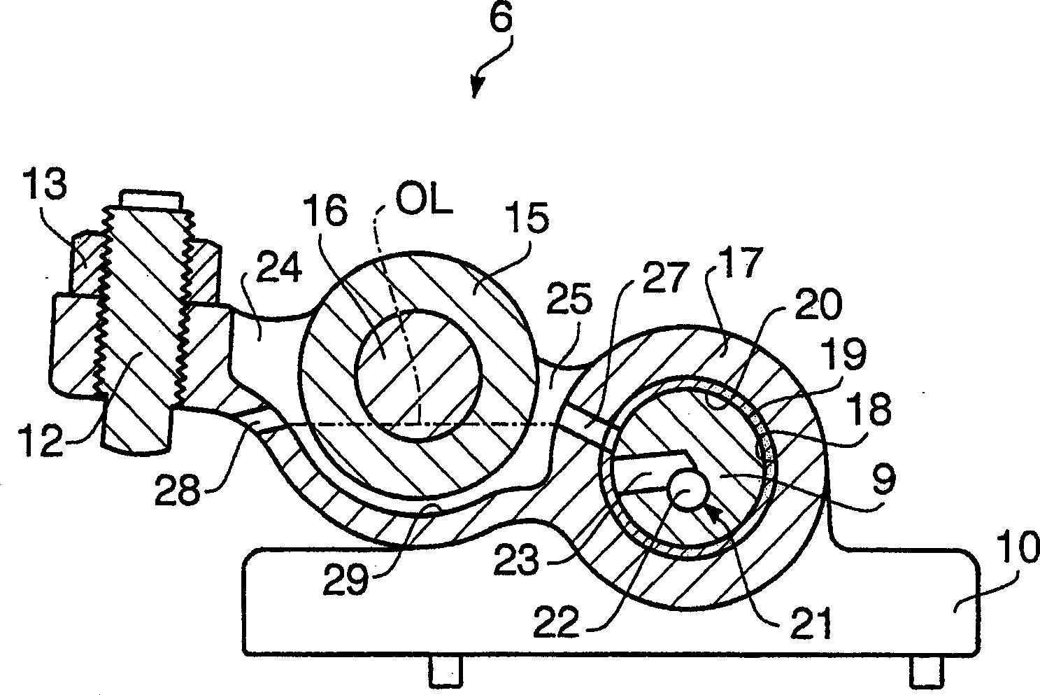
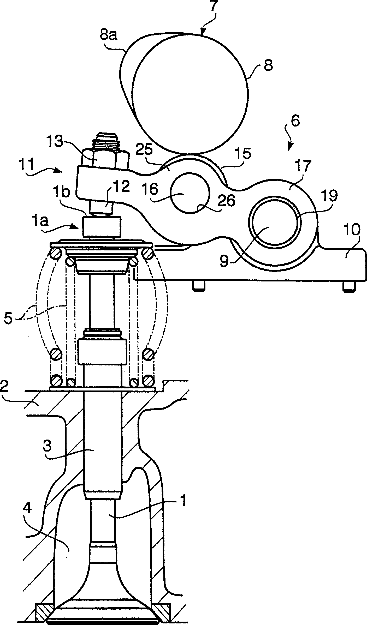
[0031] figure 2 A valve mechanism of an internal combustion engine according to the present invention is shown. The valve 1 constituting the intake or exhaust valve is supported in a valve guide 3 fixed in a cylinder head 2 so that the valve can move up and down and open and close the valve constituting the intake or exhaust port. A channel 4 inlet or outlet. The valve 1 is always driven upward by a valve spring 5, in other words, it is in the closed state of the valve; a shaft end 1a is pressed down by the rocker shaft 6, so that the valve is pressed down and the valve is opened. . The rocker arm 6 is positioned below a cam 8 of a camshaft 7 and is connected to the valve 1 in order to increase the amount by which the cam 8 lifts.

[0032] A rocker shaft 9 is fixed on the cylinder head 2 via a boss 10 so that it cannot rotate. One end of the rocker...


PUM


Abstract

The invention relates to a rocker arm for an internal combustion engine, which prevents abnormal wear of friction surfaces around the rocker arm and prevents poor lubrication when the engine is started at low temperature after a long-term shutdown, thereby improving reliability. A bag-shaped oil storage tank (24) opening upwards is arranged at the middle part of the rocker arm main body (17). A roller (15) and a roller pin (16) are arranged in the oil storage tank (24), and when the engine is stopped, they are immersed in lubricating oil in the oil storage tank (24). With the engine stopped, lubricate the area between the roller (15) and the roller pin (16). In addition, when the engine is restarted after a long-term shutdown, the area between the roller (15) and the cam (8) is lubricated with the lubricating oil adhered to the roller (25) until the lubricating oil rises. When the rocker arm (6) swings downward, lubricating oil in the oil storage tank (24) is supplied from the lubricating oil discharge passage (28) by spraying toward the shaft end of the valve.

Description

technical field [0001] This application has the advantages of the basic subject matter disclosed in Japanese Patent Application No. 2001-148157 filed on May 17, 2001, and this Japanese Patent Application is incorporated herein by reference. [0002] This invention relates to a rocker arm for an internal combustion engine, and more particularly to a rolling rocker arm including a roller in sliding contact with a camshaft. Background technique [0003] In the valve train of an internal combustion engine, it is known that a rocker arm is connected to an intake valve or an exhaust valve in order to increase the lift of the cams of the camshaft. In addition, the rocker arm is surrounded by different friction surfaces, and a lubricating mechanism described below is used to lubricate these friction surfaces. [0004] image 3 A conventional rocker arm is shown. In the rocker arm 51, one end of the main body of the rocker arm 52 (hereinafter referred to as "main body") is rotatabl...

Claims


Application Information

Patent Timeline
Patent Type & Authority Applications(China)
IPC IPC(8): F01M1/06F01L1/18F01M9/10
CPCF01L1/18F01L1/185F01L1/462F01L2810/02F01L2305/02
Inventor 饭岛章
Owner ISUZU MOTORS LTD
Why Eureka
Try Eureka