
Double-frequency pulse and double-vertical ring high-gradient magnetic separator

A high-gradient magnetic separator and double-pulse technology, applied in the field of magnetic separators, can solve problems such as increased investment and operating costs, unfavorable particle group evacuation, and large metal loss, so as to improve the separation effect, take into account the metal recovery rate, Taking into account the effect of concentrate quality

Inactive Publication Date: 2003-01-01
广东省资源综合利用研究所
View PDF1 Cites 17 Cited by
  • Summary
  • Abstract
  • Description
  • Claims
  • Application Information

AI Technical Summary

Problems solved by technology

However, the core working principle of this type of equipment is based on the fact that the pulsation direction of the slurry or water is consistent with the direction of the magnetic force line, such as Image 6 As shown, when the pulsation direction of the pulp or water is consistent with the direction of the magnetic force line, the particle group adsorbed on the surface of the medium only exists on the side along the direction of the magnetic force line. Due to the presence of a medium in front or behind the particle group, the buffering effect of the internal liquid slows down the fluid force, which is not conducive to the evacuation of the particle group. are effectively washed out
Therefore, the sorting effect is relatively limited, and the enrichment ratio and metal recovery rate cannot be taken into account. Only concentrate and tailings are produced. Only one of the concentrate grade and metal recovery rate can be guaranteed. If both are guaranteed, another section must be added. operation, increasing investment and operating costs, that is, when high-grade concentrates are obtained, the metal loss in the tailings is relatively large; on the contrary, when the tailings grades are effectively controlled, the quality of the concentrates is difficult to guarantee

Method used


Image

  • Double-frequency pulse and double-vertical ring high-gradient magnetic separator
  • Double-frequency pulse and double-vertical ring high-gradient magnetic separator
  • Double-frequency pulse and double-vertical ring high-gradient magnetic separator

Examples


Embodiment Construction

[0019] A double-frequency pulse double vertical ring high-gradient magnetic separator, comprising a sorting ring 1 and a magnetic field device 2, characterized in that the magnetic field device 2 is distributed on both sides of the sorting ring 1, which can generate magnetic lines of force running through the sorting ring 1, Below the separation ring 1 is provided at least one set of pulse devices that can cause the pulp to move in a direction perpendicular to the magnetic lines of force.

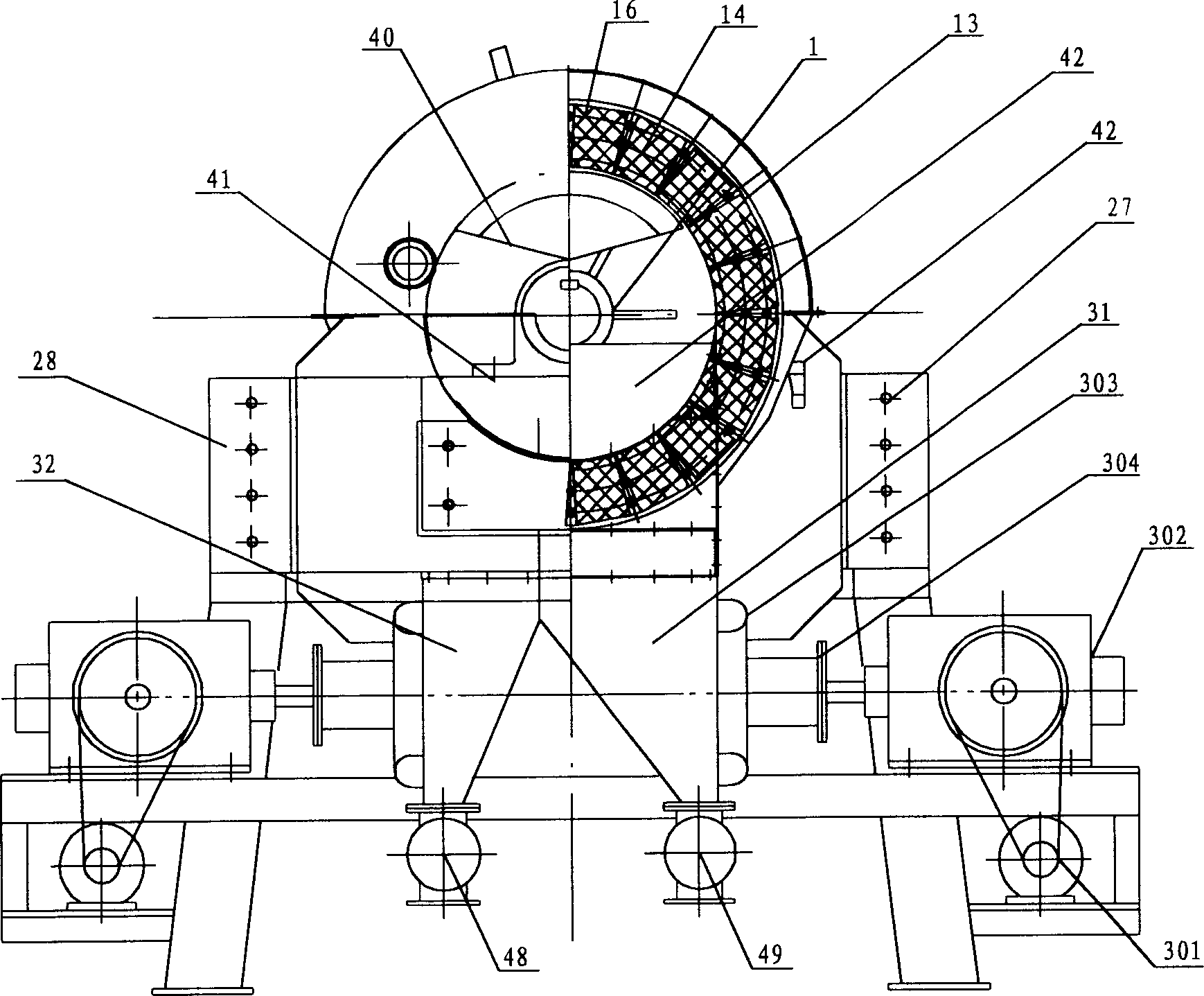
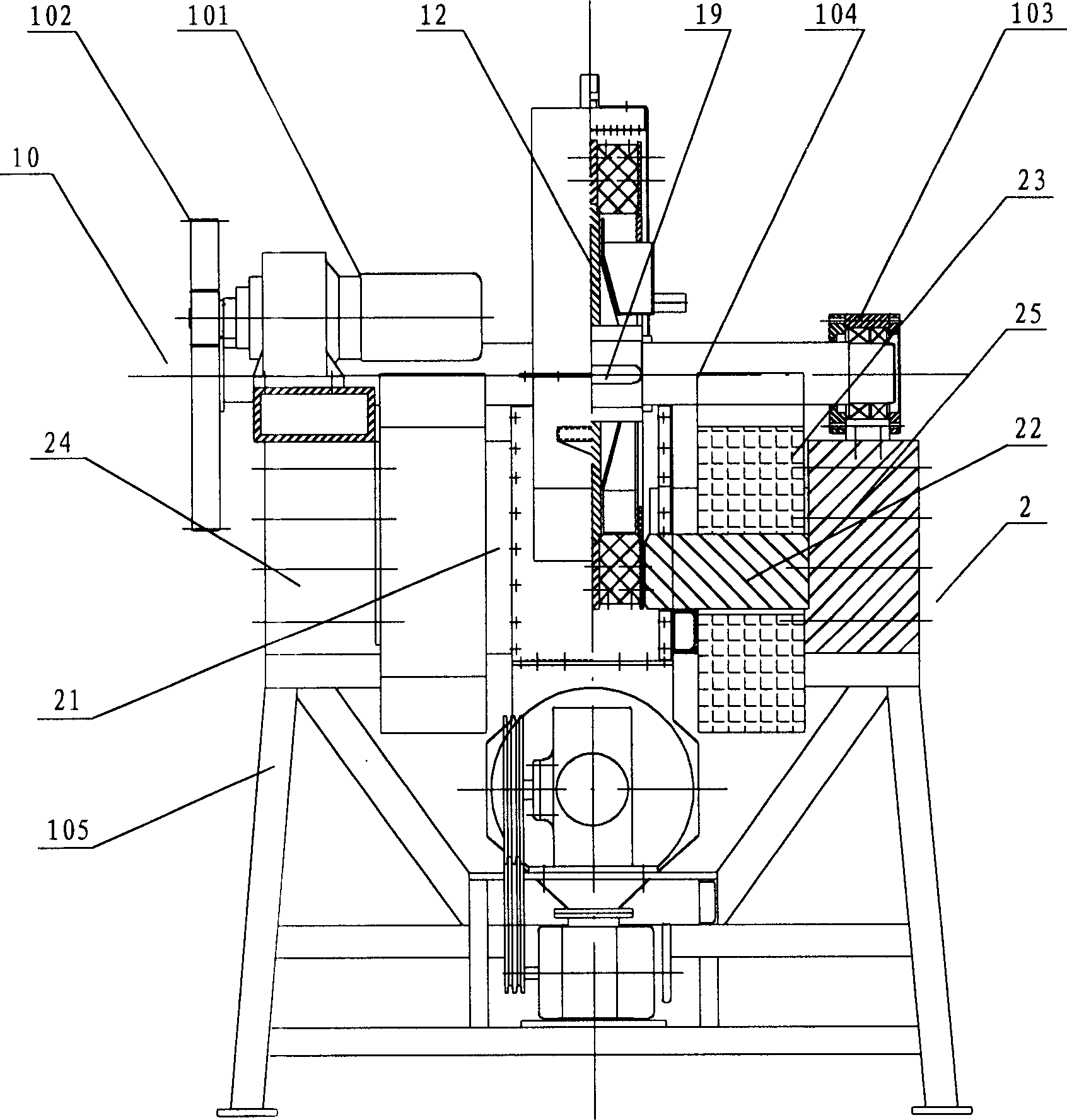
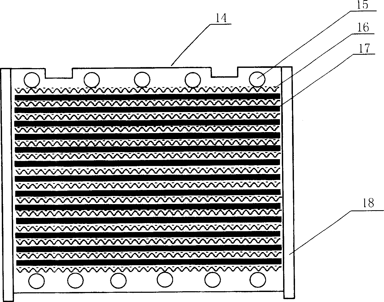
[0020] like figure 1 , figure 2 As shown, the present invention includes a sorting ring 1, a magnetic pole 2, and a double-pulse device 3. The sorting ring 1 is composed of a thick-walled ring, a thin-walled ring, a magnetic medium, and bolts, wherein the ring body 13 is a vertical double-ring structure, and the ring body 13 is a vertical double-ring structure. There is a turntable 12 that connects the double rings as a whole. The outer edge of the turntable is made of magnetically condu...


PUM


Abstract

The magnetic separator includes separating ring and magnetic field unit, the magnetic field unit is distributed beside the separating ring to produce magnetic force lines penetrating the separating ring, and the separating ring is provided with at least one pulse device to make ore pulp move in the direction perpendicular to the magnetic force lines. Owing to the combined closed magnetic field unit to produce horizontal magnetic force lines and unique double-pulse device, the particles adsorbed to the surface of the medium exist only in the side in magentic force line direction and the ore pulp reciprocates to produce fluid motion tangent to the particle side and shear and clean the particles, so that the included non-magnetic and weak magnetic adherant particles are washed out resulting in greatly raised separating effect.

Description

technical field [0001] The invention relates to a magnetic separator for ore dressing, in particular to a double-frequency pulse double vertical ring high-gradient magnetic separator. Background technique [0002] The high-gradient magnetic separation theory has brought a qualitative leap to the field of magnetic separation, increasing the types of minerals that can be magnetically separated, and widening the upper and lower limits of particle size. [0003] Early high-gradient magnetic separators are periodic, also known as magnetic filters, and this type of equipment is widely used in occasions with extremely low magnetic content and very fine particle size. [0004] The continuous high gradient magnetic separators that appeared immediately include electromagnetic flat ring strong magnetic high gradient magnetic separators, permanent magnet and electromagnetic double vertical ring high gradient magnetic separators. Electromagnetic flat-ring high-gradient magnetic separato...

Claims


Application Information

Patent Timeline
IPC IPC(8): B03C1/025
Inventor 汤玉和张鸿柱赵明何健全向发柱郑承美
Owner 广东省资源综合利用研究所
Learn More