Electric machine for electrodynamic steering gear

An electric power steering and rotor technology, applied in the direction of electric steering mechanism, electromechanical devices, electric components, etc., can solve the problems of large radial size of the motor 2, low operating efficiency, and difficult connection

Inactive Publication Date: 2003-01-01
MITSUBISHI ELECTRIC CORP
View PDF0 Cites 23 Cited by
  • Summary
  • Abstract
  • Description
  • Claims
  • Application Information

AI Technical Summary

Problems solved by technology

[0008] The outer periphery of the conventional motor 2 is composed of the rear bracket 12 for fixing the rotation sensor 15, the frame 5 for fixing the stator 6, the front bracket 9 for fixing the load-side bearing 10, and the waterproof cover 16. There are many components, so there are gaps between the components. The assembly process and the problem that there are many O-rings 27, 28, 29 between the components
[0009] In addition, the terminals 21 on the stator side of the terminal block 14 extend radially, and there is a problem that the radial dimension of the motor 2 is large.
[0010] In addition, since each terminal 21 on the stator side is in the form of a thin plate, when the phase conductors 23 are directly connected to each terminal 21 on the stator side by welding or the like, there is a problem that the connection operation space is narrow and the connection is difficult.
[0011] In addition, a plurality of sensor signal wires 24 need to pass through the grommet 25 respectively, and the working efficiency is low.
[0012] Additionally, if Figure 13 As shown, the grommet 25 for the sensor signal line 24 to pass through and the grommet 22 for each phase wire 23 to pass through are respectively provided, so there is also the problem of a large number of components.

Method used


Image

  • Electric machine for electrodynamic steering gear
  • Electric machine for electrodynamic steering gear
  • Electric machine for electrodynamic steering gear

Examples


Embodiment Construction

[0039] Embodiment 1

[0040] Embodiments of the present invention will be described below, and the same components and parts as those of the conventional electric power steering motor are denoted by the same symbols.

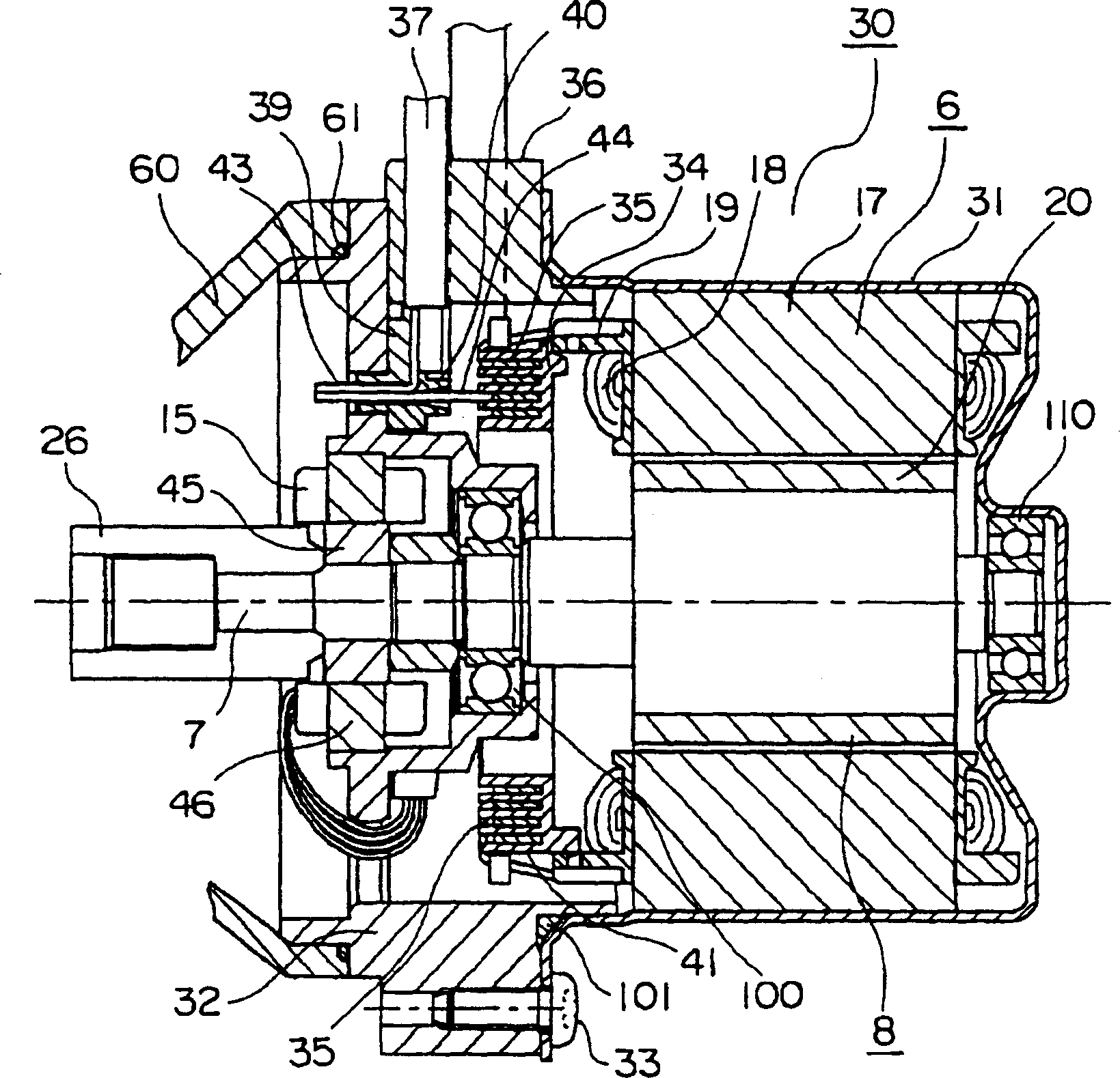
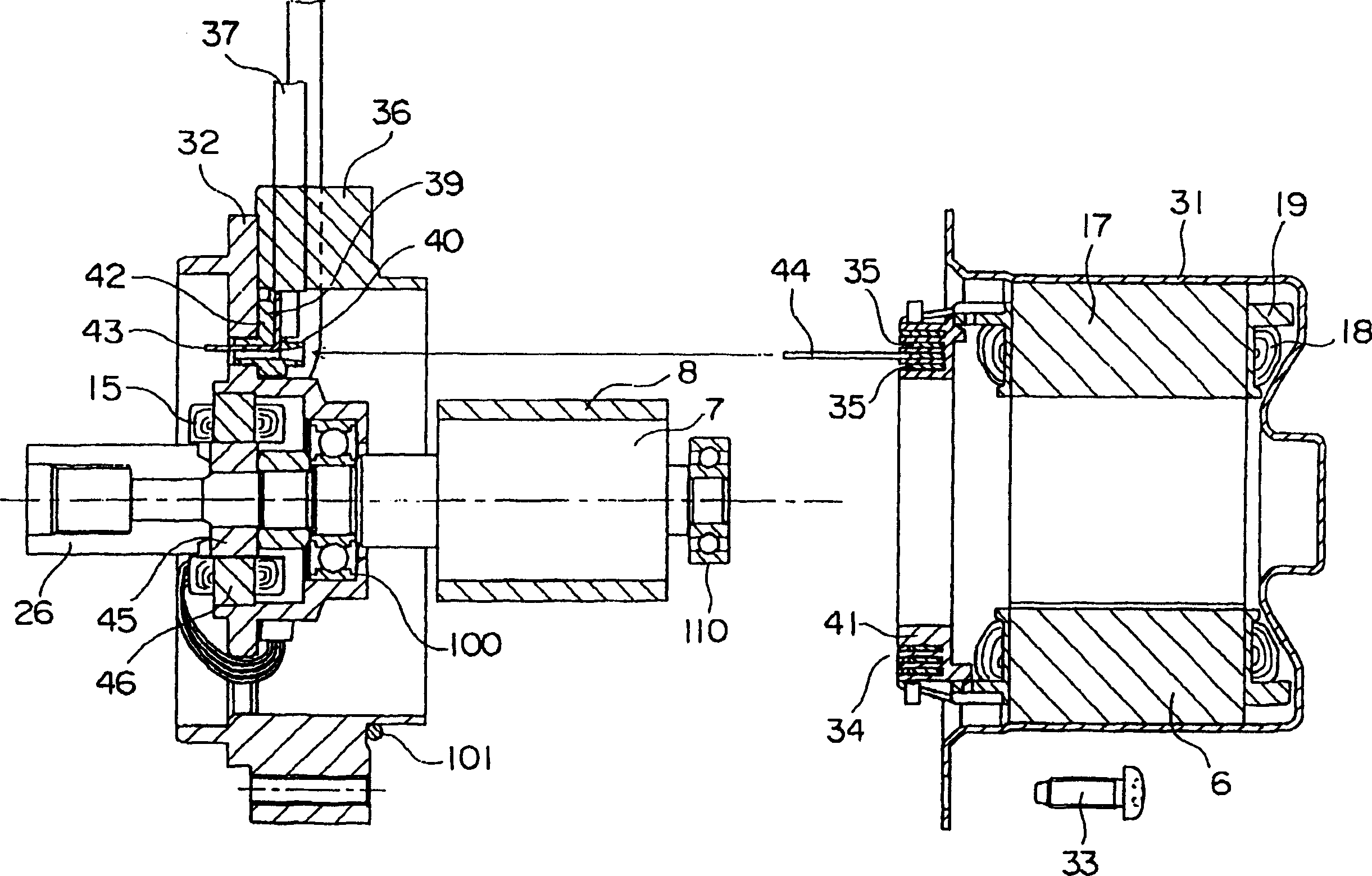
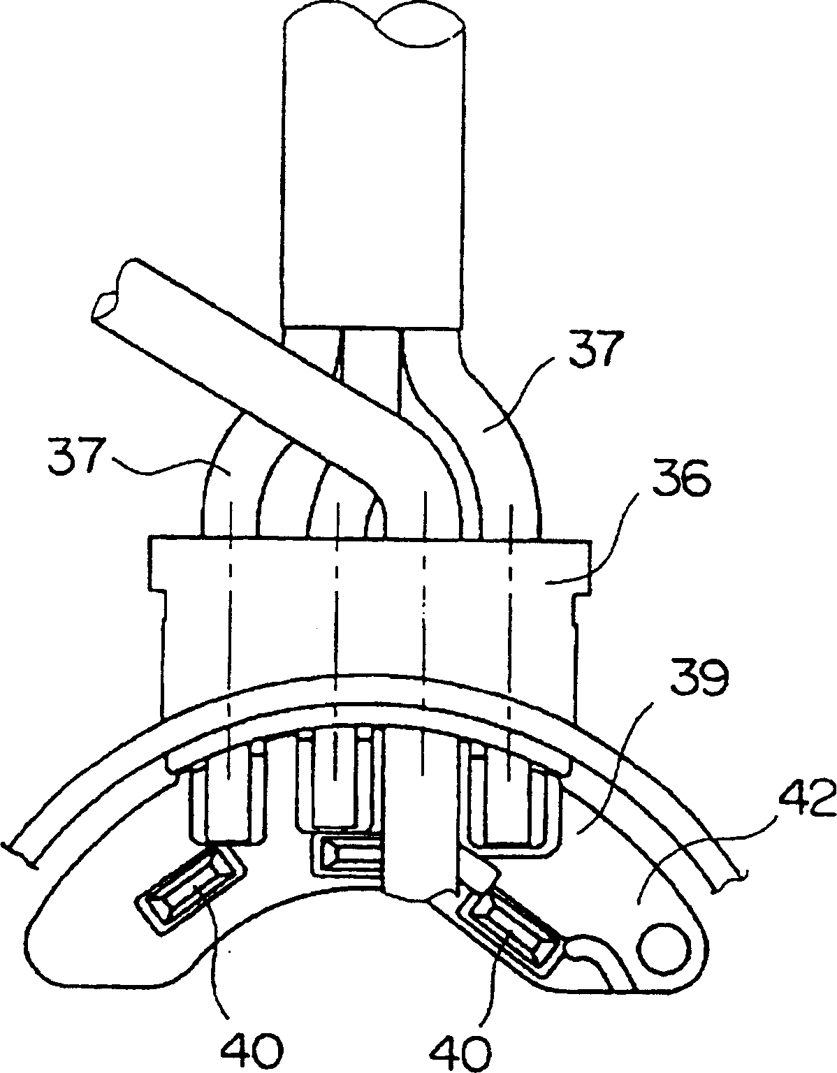
[0041] figure 1 is a side sectional view showing a motor (hereinafter referred to as "motor") 30 for electric power steering, figure 2 yes figure 1 An exploded view of the motor 30, image 3 yes figure 1 Front view of the connection base plate 39, Figure 4 yes image 3 The sectional view of the main part of the connecting bottom plate 39, Figure 5 yes figure 1 Top view of grommet 36.

[0042] The motor 30 is provided with: a bottomed cylindrical frame 31; a stator 6 fixed on the frame 31; a rotor 8 made of a shaft 7 and a cylindrical magnet forming N magnetic poles and S magnetic poles; The bracket 32 ​​fixed by bolts 33; the resolver type rotation sensor 15 embedded in the bracket 32; the bracket side bearing 100 embedded in the bracket 32; the ...


PUM


Abstract

A motor for use with a motorized power steering apparatus is provided in which the number of component members can be reduced, and workability in assembling the component members can be improved, while enabling miniaturization of the entire motor. The motor includes a bottomed cylindrical frame (31), a bracket (32) fixedly secured to the frame (31), a rotating element (8) having a shaft (7) rotatably supported by a frame side bearing (110) fixedly mounted on the frame (31) and a bracket side bearing (100) fixedly mounted on the bracket (32), a stationary element (6) fixedly attached to the frame (31) around an outer periphery of the rotating element (8) and having a stator winding (18) wound therearound, a rotation sensor (15) provided on the bracket (32) at a housing side of the bracket side bearing (100), and a plurality of sensor signal wires (38) for supplying and receiving signals to and from the rotation sensor (15).

Description

technical field [0001] The present invention relates to an electric power steering motor (hereinafter referred to as "motor") that enhances steering force of a vehicle. Background technique [0002] Figure 9 Represents the perspective view of the motor 2 located near the axle 1, such as Figure 10 As shown, the worm wheel 4 meshes with the worm 3 connected to the motor 2 . The worm screw 3 and the worm gear 4 that transmit the steering force to the steering wheel are contained in the housing 60, and the O-ring is used to ensure the sealing between the motor 2 and the housing 60 . [0003] Figure 11 is a side sectional view of a conventional motor 2, Figure 12 yes Figure 11 An exploded view of Motor 2. The motor 2 is provided with: a cylindrical frame 5, a stator 6 fixed on the frame 5, a rotor 8 composed of a rotating shaft 7 and cylindrical magnets forming N magnetic poles and S magnetic poles, mounted on one side of the frame 5 and The front bracket 9 whose cente...

Claims


Application Information

Patent Timeline
Patent Type & Authority Applications(China)
IPC IPC(8): B62D5/04H02K3/50H02K5/04H02K5/22H02K11/00
CPCH02K3/50H02K2203/09H02K11/0015H02K5/225H02K11/21H02K3/522H02K5/04
Inventor 冈崎正文柳生泰秀米贺多秀树高木哲尚逸见晋介阿久津悟杉山武史
Owner MITSUBISHI ELECTRIC CORP
Why Eureka
Try Eureka