Overload protection device, electric compressor and refrigerating air-conditioner apparatus
An overload protection and motion device technology, applied in the field of electric compressors, refrigeration and air conditioning devices, and overload protection devices, can solve problems such as reducing coil resistance, increasing current, and welding, achieving reliable current cutoff and preventing arc generation. , The effect of reliable current cut off
- Summary
- Abstract
- Description
- Claims
- Application Information
AI Technical Summary
Problems solved by technology
Method used
Image

Examples
Embodiment approach 1
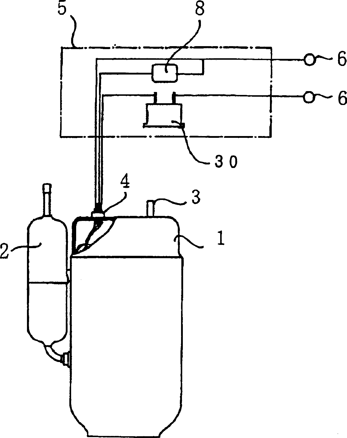
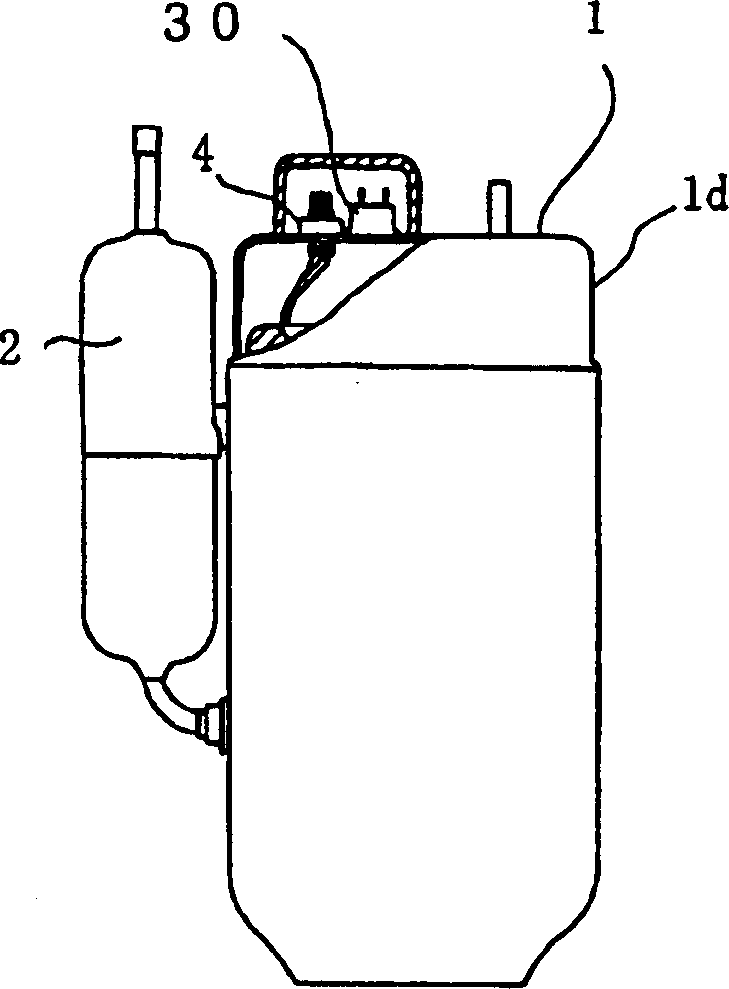
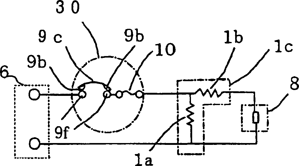
[0082] Next, explain Figure 1 ~ Figure 7 The overload protection device of Embodiment 1 of the present invention is shown. figure 1 It is a schematic diagram showing the connection of the overload protection device to the control circuit of the refrigeration and air-conditioning unit, figure 2 It is a schematic diagram showing that the overload protection device is installed on the outer surface of the electric compressor, image 3 It is a circuit diagram for a single-phase power supply assembled with an overload protection device, Figure 4 It is a circuit diagram for a three-phase power supply assembled with an overload protection device, Figure 5 Is a longitudinal section view of the overload protection device, Figure 6 Is viewed from below Figure 5 A view of the I-I section, Figure 7 Viewed from above Figure 5 A view of the II-II section.
[0083] In these figures, 1 is a hermetic electric compressor with a built-in electric motor 1c composed of a main coil 1a and an a...
Embodiment approach 2
[0108] Fig. 8 is a longitudinal sectional view of an overload protection device according to Embodiment 2 of the present invention, Picture 9 It is a schematic view of the section III-III of Fig. 8 viewed from below, Picture 10 It is the IV-IV cross-sectional view of Fig. 8 viewed from above. In the figure, 7 is a storage container, which is composed of a container 7a and a lid 7b, and is formed of a heat-resistant insulating material such as synthetic resin. 9 is a first heat-sensitive motion device that is reversibly supported and fixed by a central fixed shaft 9a in the container 7, and is composed of a disc-shaped heat-sensitive motion plate 9c having a pair of movable contacts 9b and corresponding to the above-mentioned movable A pair of fixed contacts 9f provided as a contact 9b is configured, and the fixed contact 9f is fixed to a fixed terminal 9e penetratingly attached to an arbitrary position on the inner bottom surface 7c of the container 7a.
[0109] 13 is a linear h...
Embodiment approach 3
[0117] In the first and second embodiments, the overload protection device 30 installed on the outside of the airtight container 1d of the compressor or used in the control circuit 5 of the refrigerating and air-conditioning unit is described. However, in the third embodiment of the present invention, Here, the overload protection device 30 used in the airtight container 1d of the compressor will be described.
[0118] Picture 11 It is a schematic diagram of the overload protection device of the third embodiment of the present invention mounted on the motor coil in the electric compressor, Picture 12 It is a schematic view showing that the overload protection device is mounted on the glass sealed terminal 4 part on the inner upper surface of the airtight container 1d of the electric compressor. In addition, Figure 13 Is a side view showing the overload protection device of the third embodiment of the present invention, Figure 14 Is a plan view showing the overload protection ...
PUM
 Abstract
Description
Claims
Application Information
 - R&D
- Intellectual Property
- Life Sciences
- Materials
- Tech Scout
- Unparalleled Data Quality
- Higher Quality Content
- 60% Fewer Hallucinations
Browse by: Latest US Patents, China's latest patents, Technical Efficacy Thesaurus, Application Domain, Technology Topic, Popular Technical Reports.
© 2025 PatSnap. All rights reserved.Legal|Privacy policy|Modern Slavery Act Transparency Statement|Sitemap|About US| Contact US: help@patsnap.com