
Conditioner for polishing pad and method for manufacturing the same

A technology for polishing pads and regulators, which is used in the manufacture of semiconductor/solid-state devices, wheels with flexible working parts, and manufacturing tools, etc. question

Inactive Publication Date: 2003-01-15
二和DIAMOND工业株式会社
View PDF0 Cites 27 Cited by
  • Summary
  • Abstract
  • Description
  • Claims
  • Application Information

AI Technical Summary

Problems solved by technology

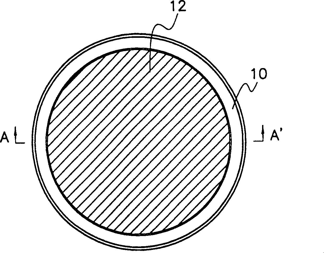
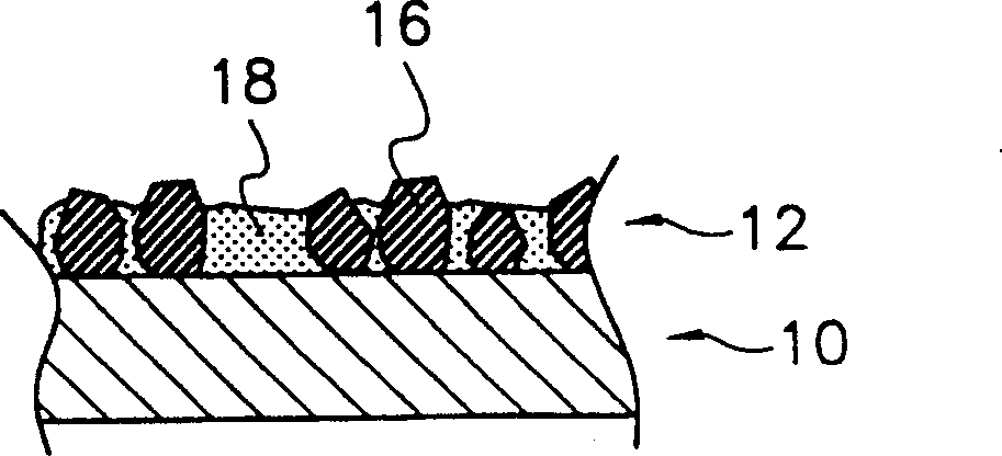
In the on-site adjustment process of implementing oxide or metal CMP, because the polishing process and the adjustment process are carried out simultaneously, the bonding metal 18 that fixes the diamond particles 16 is also affected by the cutting fluid, and the result is that the diamond particles 16 are removed from the adjuster. shedding frequently on the surface
In addition, during the on-site adjustment of metal CMP, the highly acidic cutting fluid used in the processing has a tendency to corrode the bonding metal 18 to weaken the bonding effect, which will eventually lead to the loss of diamond particles 16
[0009] The detached diamond particles 18 are usually attached to the surface of the polishing pad, and have severe scratches on the wafer surface during polishing, which will lead to a high rate of defective products during semiconductor processing
Therefore, the polishing pad must be frequently reconditioned
[0010] In addition, during metal CMP field conditioning, metal ions separated from the corroded bond metal 18 often attach to the metal wires of the wafer circuit, which will cause short circuits
In addition, the metal ions separated from the in-situ conditioning process are basically attributed to the metal ion contamination of the wafer, and since the semiconductor defects caused by the contamination can only be found in the subsequent processing stage, the losses caused by the defects The industrial impact is considerable

Method used


Image

  • Conditioner for polishing pad and method for manufacturing the same
  • Conditioner for polishing pad and method for manufacturing the same
  • Conditioner for polishing pad and method for manufacturing the same

Examples


Embodiment 1

[0054] Figure 2A to Figure 2F A regulator having a disc shape according to a first preferred embodiment of the present invention is shown in , which regulator includes an integral part 20 , a cutting part 22 and a substrate 50 .

[0055] like Figure 2A to Figure 2D As shown, the cutting portion 22 has a large number of rectangular geometric protrusions 28 forming regional units in the form of cross-bands on the surface of the substrate 50, Figure 8A and Figure 8B are enlarged perspective and cross-sectional views in which the cross-band form of the rectangular geometric protrusions 28 of the cutting portion 22 is closely shown.

[0056] Substrate 50 is preferably made of a ceramic material such as Si or Si 3 N 4 . Or at least one ceramic material selected from the following group of ceramic materials, which include Al 2 o 3 , AlN, TiO 2 , ZrOx, SiO 2 , SiC, SiOxNy, WNx, Wox, DLC(diamond like coating), BN and Cr 2 o 3 . Alternatively, substrate 50 may be made of ...

Embodiment 2

[0065] In this embodiment, various and optional arrangements of the geometric protrusions on the surface of the substrate can be realized by changing the arrangement and structure of the grooves. like Figure 2EAs shown, grooves of the same shape may be formed on the cut portion 22a in the surface of the substrate with the same width and / or depth. Figure 7A and Figure 7B shown in the Figure 2E Enlarged perspective and cross-sectional views of the geometric protrusion arrangement formed by the grooves in . For this arrangement, it is preferable to make the groove 26a smaller than Figure 2A Grooves 26 are shown having a greater width and / or depth to effectively expel polishing pad debris from the surface of cutting portion 22a.

Embodiment 3

[0067] In this embodiment, various shapes of geometric protrusions can be realized. The shape of the geometric protrusion 28 is not limited to a rectangular shape, and alternatively, such as Figure 2F As shown, the geometric protrusion 28b formed on the cutting portion 22b has a cylindrical shape. Figure 9A and Figure 9B shows enlarged perspective and cross-sectional views with a cutting portion 22b formed by a cylindrical geometric protrusion 28b, similar to a substrate having a rectangular geometric protrusion, a substrate having a cylindrical geometric protrusion 28b on its cutting portion 22b is also There is a diamond layer 52 . The designed arrangement of the cylindrical geometric protrusions 28b can be in the same arrangement as the first and second preferred embodiments, or can be achieved by having a strip extending radially from the center of the substrate.


PUM


Abstract

A ceramic disc-shaped substrate is formed with geometrical protrusions of a uniform height on at least one side. A cutting portion (22) is formed, with a diamond layer of a uniform thickness formed on all the surface of the side of the substrate with protrusions. The protrusions have a flat upper surface, or the upper surface may comprise several smaller protrusions formed by recessed grooves. The cutting portion makes line and surface contacts with the polishing pad surface. An independent claim is included for a method of manufacturing a conditioner for a polishing pad

Description

technical field [0001] The present invention relates to a conditioner for a polishing pad and a method of making the same, and more particularly to a conditioner for a polishing pad used in a chemical mechanical polishing (CMP) process and to making the conditioner device method. Background technique [0002] In general, chemical mechanical polishing is widely used in the processing of semiconductor devices to obtain smooth and flat wafer surfaces. Typically, a wafer to be polished is held by a carrier on a polishing pad placed on a rotary table (not shown), and then passed through the The wafer is polished by the relative movement of the table and the carrier. Conventional polishing pads used in chemical mechanical polishing processes typically contain a number of small holes with a diameter size of 30-70 m to exhibit a pumping effect to achieve high removal rates when pressure is applied to the polishing pad. However, after prolonged use, the hole becomes worn and becom...

Claims


Application Information

Patent Timeline
Patent Type & Authority Applications(China)
IPC IPC(8): B24B53/12B24B53/007B24D3/00B24D7/06B24D11/00B24D13/14H01L21/304
CPCB24B53/12B24B53/017B24B37/26B24D11/001B24D11/00
Inventor 明汎英刘寿男
Owner 二和DIAMOND工业株式会社
Learn More