Power enlargement type apparatus for removing dust of ejecting drilling

A jet-suction drilling and power technology, applied in boring/drilling, drilling/drilling equipment, components of boring machine/drilling machine, etc., can solve the problems of insufficient chip extraction force, DF system cannot replace gun drilling system, etc.

Inactive Publication Date: 2003-01-29
王峻
View PDF0 Cites 10 Cited by
  • Summary
  • Abstract
  • Description
  • Claims
  • Application Information

AI Technical Summary

Problems solved by technology

However, the DF system cannot replace the gun drilling system because of the insuffici

Method used


Image

  • Power enlargement type apparatus for removing dust of ejecting drilling
  • Power enlargement type apparatus for removing dust of ejecting drilling

Examples


Embodiment Construction

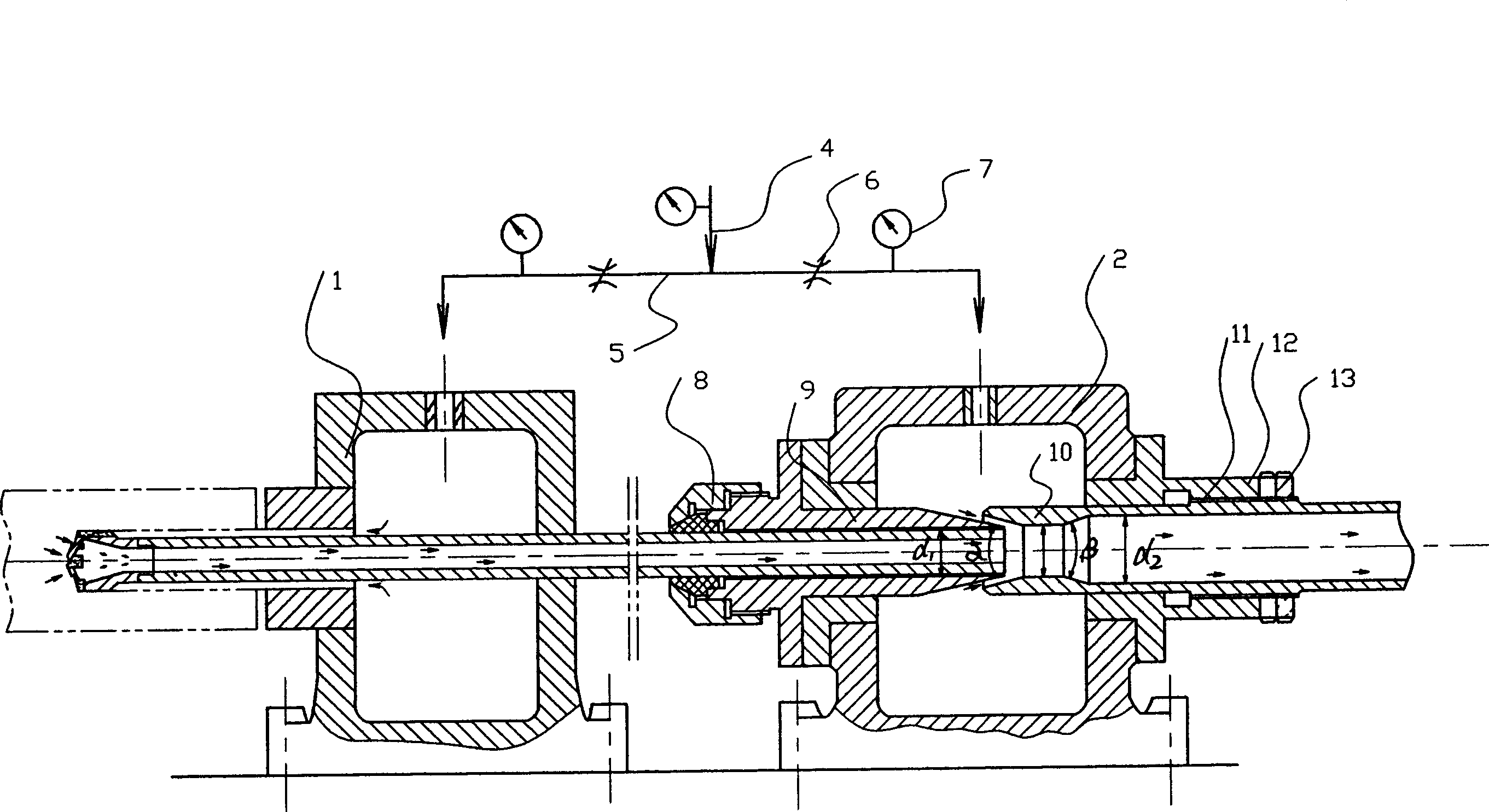
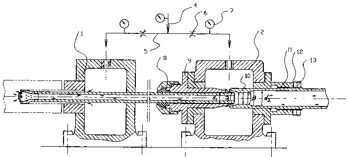
[0012] figure 1 Among them, the chip extraction device is mainly composed of an oil feeder 1 and a chip extractor 2. The structural feature is that the chip extractor 2 and the oil feeder 1 are connected to the main oil pipeline 4 on each branch oil pipeline 5. A fuel-saving valve 6 is installed in series, and a pressure gauge 7 is installed behind each fuel-saving valve 6, and a pressure gauge 7 is also equipped on the main oil pipeline, and the entire oil circuit is supplied with oil by an oil pump. The chip extractor 2 is composed of a sealed oil tank 8 and a front nozzle 9 and a rear nozzle 10 which are respectively sealed and assembled on the front wall and the rear wall of the sealed oil tank 8. The rear nozzle 10 is sealed by a sealing sleeve fixedly assembled on the rear wall of the sealed oil tank 8. Assembled in the sealing sleeve 12, the cylindrical surface of the front part of the rear nozzle 10 seals with the inner tube surface of the sealing sleeve 12 through the...


PUM


Abstract

A separate-regulatable powder-boosting type drilling chip extracting device for ejection drill is composed of oil delivering unit and drilling chip extractor. The sealed oil tanks for the said oil delivering unit and drilling chip extractor are respectively connected to the oil trank of oil pump via their branch pipes with throttle valves. Regulating of throttle valves can make the device be in optimal state to extract the drilling chip.

Description

Technical field: [0001] The invention relates to a chip extraction device for an internal chip removal jet suction drill in the field of machinery, in particular to a split-adjustment power supplement type jet suction drill chip extraction device. Background technique: [0002] Deep hole processing technology developed to the mid-1970s, and Nippon Metallurgical Co., Ltd. launched a single-tube ejector drilling system (Double Feeder System, DF system for short). In this system, a set of chip extractor is added at the end of the single-pipe chip removal drill. The chip extractor is composed of a sealed oil tank and a pair of conical nozzle bodies corresponding to convex and concave. The DF system divides the cutting fluid into two branches: the front branch accounts for 3 / 2 of the total cutting fluid, flows into the oil feeder, the cutting fluid flows into the cutting part from the outside of the drill pipe, and then discharges chips backward through the inner cavity of the dr...

Claims


Application Information

Patent Timeline
IPC IPC(8): B23B41/02B23B47/34
Inventor 王峻
Owner 王峻
Why Eureka
Try Eureka