Radio base station appts. and communication terminal appts.
A wireless base station and communication terminal technology, applied in wireless communication, communication between multiple stations, and selection devices, etc., can solve the problems of wasting frequency bands, wasting frequency bands, and not being able to fully use the allocated frequency bands, etc.
- Summary
- Abstract
- Description
- Claims
- Application Information
AI Technical Summary
Problems solved by technology
Method used
Image
Examples
Embodiment 1
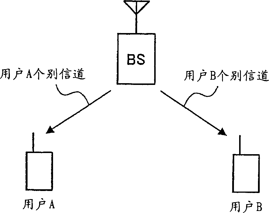
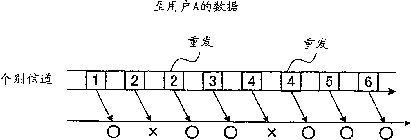
[0032] Such as Figure 4 As shown, in this embodiment, the following situation is described: the base station (BS) performs wireless communication with the communication terminal of user A and the communication terminal of user B, the data is sent by a dedicated channel, and the retransmission data is sent by a common channel.
[0033] Figure 5 is a block diagram showing the configuration of the radio base station apparatus according to Embodiment 1 of the present invention.
[0034] User A transmission data (transmission data other than retransmission data) generated by a data generation unit (not shown) is sent to dedicated channel spreading unit 201, and subjected to spread modulation processing using code #0. The spread-modulated data is sent to the quadrature modulation unit 204 , where quadrature modulation such as QPSK (Quadrature Phase Shift Keying; Quadrature Phase Shift Keying) is performed, and output to the multiplexing unit 207 .
[0035] User B transmission da...
Embodiment 2
[0064] In this embodiment, a case will be described in which the transmission power of the common channel for transmitting retransmission data is adjusted according to the retransmission status.
[0065] Figure 9 It is a block diagram showing the configuration of a radio base station apparatus according to Embodiment 2 of the present invention. exist Figure 9 in, right with Figure 5 The same part is appended with Figure 5 The same reference numerals are used, and their detailed descriptions are omitted.
[0066] Figure 9 The wireless base station device shown is in addition to Figure 5 In addition to the configuration of the shown radio base station apparatus, it further includes a retransmission count counter 602 that measures the retransmission count, and a power adjustment unit 601 that adjusts transmission power according to the retransmission count.
[0067] In this embodiment, power adjustment is only performed on the channel for sending retransmission data a...
Embodiment 3
[0075]In this embodiment, a case where transmission data other than retransmission data is transmitted using a common channel will be described.
[0076] Figure 10 It is a block diagram showing the configuration of a radio base station apparatus according to Embodiment 3 of the present invention. exist Figure 10 in, right with Figure 5 The same part is appended with Figure 5 The same reference numerals are used, and their detailed descriptions are omitted. Figure 11 is a block diagram showing the configuration of a communication terminal device according to Embodiment 3 of the present invention. exist Figure 11 in, right with Figure 6 The same part is appended with Figure 6 The same reference numerals are used, and their detailed descriptions are omitted.
[0077] Figure 10 The wireless base station unit shown includes: replacing Figure 5 The individual channel spreading units 201 and 202 of the shown wireless base station apparatus, the common channel spre...
PUM
 Abstract
Description
Claims
Application Information
 - R&D
- Intellectual Property
- Life Sciences
- Materials
- Tech Scout
- Unparalleled Data Quality
- Higher Quality Content
- 60% Fewer Hallucinations
Browse by: Latest US Patents, China's latest patents, Technical Efficacy Thesaurus, Application Domain, Technology Topic, Popular Technical Reports.
© 2025 PatSnap. All rights reserved.Legal|Privacy policy|Modern Slavery Act Transparency Statement|Sitemap|About US| Contact US: help@patsnap.com


