Automatic scanning head optics regulating mechanism

An adjustment mechanism, optical automatic technology, applied in optics, optical components, instruments, etc., can solve the problems of high requirements for work proficiency, increased production costs, unsatisfactory and other problems, and achieves short adjustment time for optical mechanisms, improved position control accuracy, The effect of highlighting creative features

Inactive Publication Date: 2003-03-19
力捷电脑(中国)有限公司
View PDF0 Cites 3 Cited by
  • Summary
  • Abstract
  • Description
  • Claims
  • Application Information

AI Technical Summary

Problems solved by technology

[0004] 1. The adjustment accuracy is not easy to control
For example, in charge coupler adjustment, the current SER tolerance range is (-1, +1), SKEW tolerance range is (-0.4, +0.4), and its center value is 0, but practice has proved that the CP and CPK of the manual adjustment process (process Capability analysis index) value is not ideal; in lens adjustment, theoretically, the higher the MTF value, the better, and the more average the MTF value of each area, the better, but the forward and backward feed of the lens when manually adjusting with the adjustment stick The amount cannot be precisely controlled, and there are often over-tuning or under-tuning phenomena, and it is difficult to make the MTF value of each area reach the best or relatively average state
[0005] 2. Long adjustment cycle and low efficiency
Manual adjustment needs to adjust the optical mechanism from a position that is relatively far away to the acceptable range, so it takes a long time to adjust
[0006] 3. The requirements for the proficiency of the operation are high, and the education and training of the operators takes a long time
These factors are not only detrimental to improving product quality, but also increase the production cost of the enterprise accordingly
[0007] 4. The operator has a high probability of making mistakes due to work fatigue

Method used


Image

  • Automatic scanning head optics regulating mechanism
  • Automatic scanning head optics regulating mechanism
  • Automatic scanning head optics regulating mechanism

Examples


Embodiment

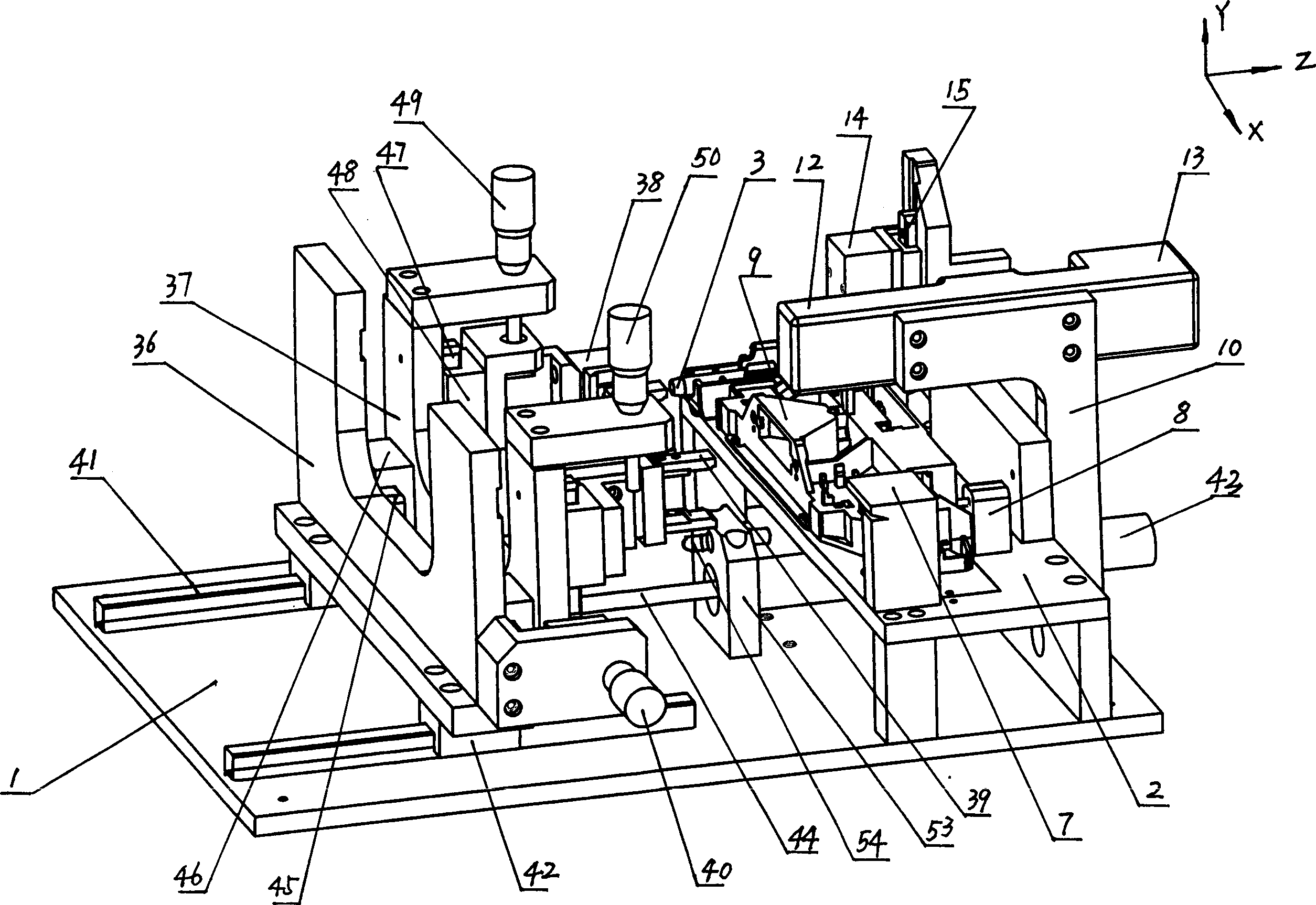
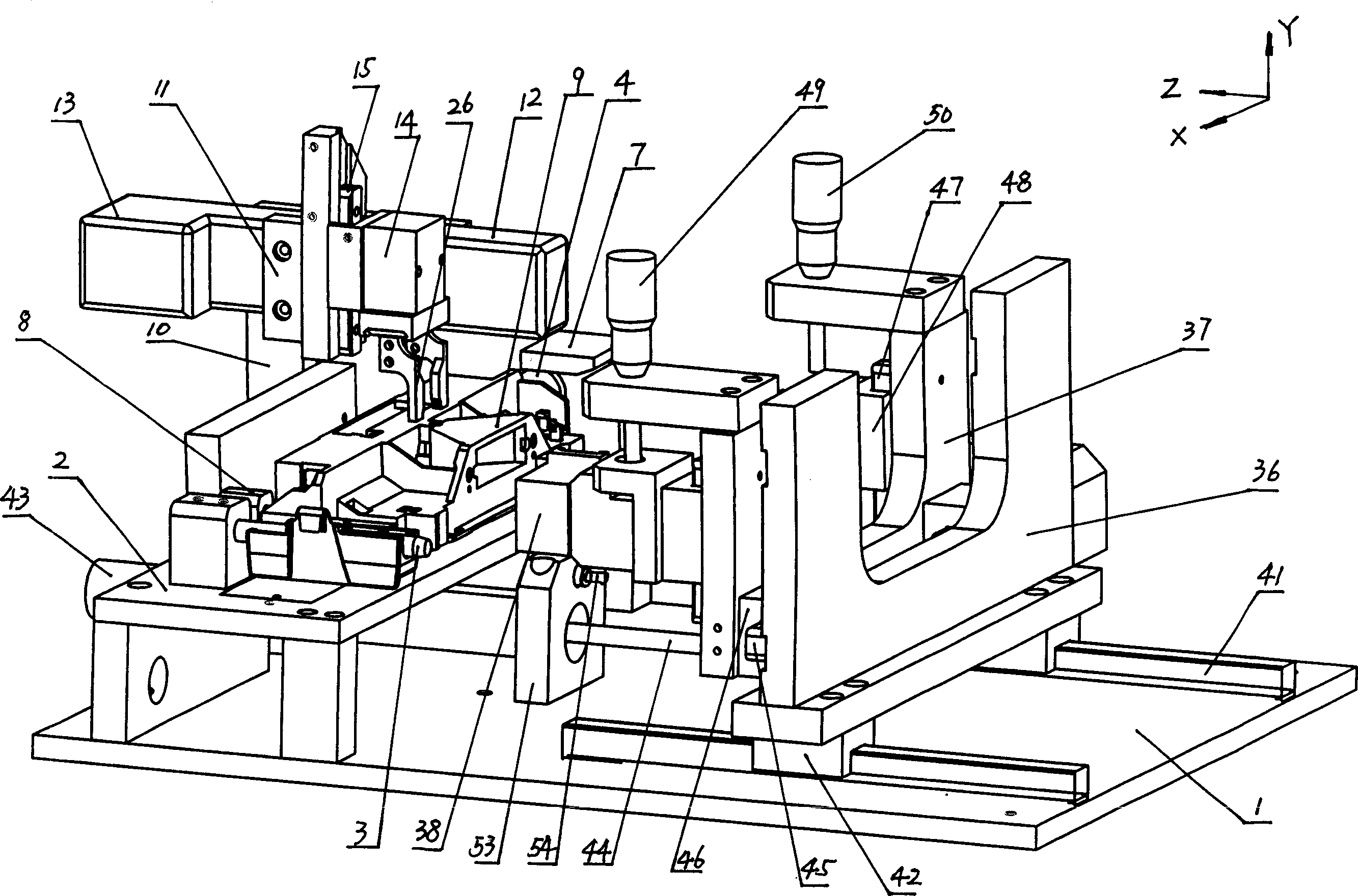
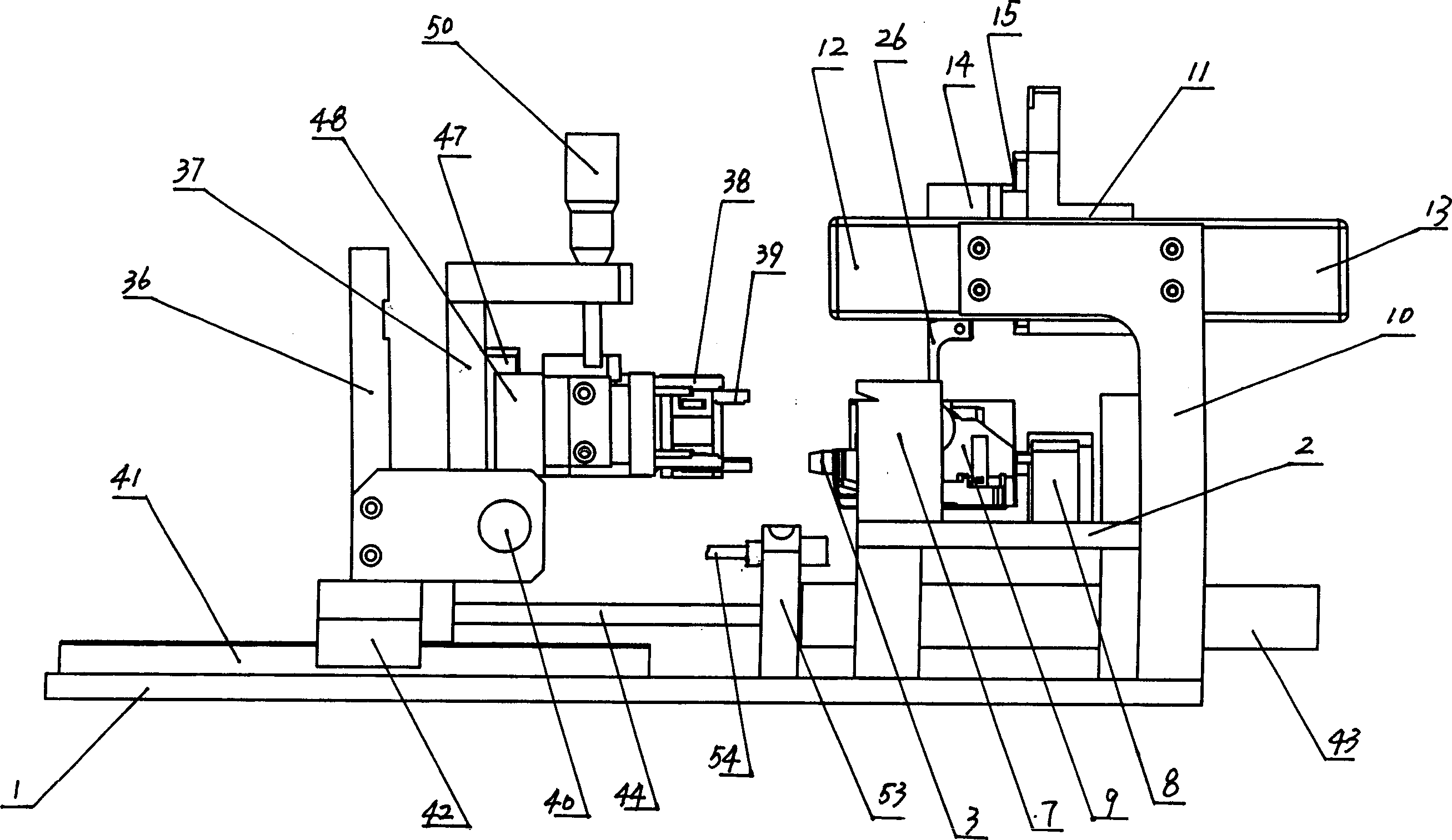
[0062] Example: see attached Figure 1 to Figure 5 As shown, a scanning head optical automatic adjustment mechanism is provided on a base 1 simultaneously with a scanning head positioning mechanism, a lens adjustment mechanism and a charge coupler adjustment mechanism. The following describes each of these three institutions:

[0063] 1. Scanning head positioning machine

[0064] See attached Figure 6 ~ Figure 8As shown, the mechanism is provided with a positioning frame 2, and the positioning frame 2 is provided with a three-dimensional space positioning reference and a pressing device. The three-dimensional space positioning reference is composed of a Z-direction positioning axis 3, a rotation positioning structure around the Z direction, and a moving positioning structure along the Z direction. One end of the Z-direction positioning shaft 3 is fixed on the positioning frame 2 through a fixed block, and the other end is suspended in the air so as to pass through the long...


PUM


Abstract

The present invention is the automatic optical modulating mechanism for scanning head in scanner instrument. The scanning head is fixed integrally on one base via a positioning mechanism, and the optical modulating mechanism includes one automatic lens regulating mechanism and one automatic CCD/B regulating mechanism for fast, precise and automatic regulation. When the automatic modulating mechanism is combined with PC, PLC and relevant software, the whole process of data acquisition, analysis, processing, controlling and regulation may be completely automatized to optimize the result.

Description

technical field [0001] The present invention relates to the optical automatic adjustment device (Auto-OMA) of relevant scanning head in the scanner, particularly relate to the optical automatic adjustment mechanism of relevant scanning head in this optical automatic adjustment device, this mechanism comprises the automatic adjustment mechanism of lens (Lens), electric charge The automatic adjustment mechanism of the coupler (CCD / B) and the automatic positioning mechanism of the scanning head, etc. Background technique [0002] The scanning head is the core of the photoelectric conversion mechanism of the scanner. It is mainly composed of a chassis, a lens and a charge coupler (CCD / B). When assembling, the lens is inserted into the lens hole of the chassis. The coupler (CCD / B) is installed on the imaging position of the lens to form a photoelectric scanning component. The optical effect of the scanning head is not only related to each optical image...

Claims


Application Information

Patent Timeline
Patent Type & Authority Applications(China)
IPC IPC(8): G02B26/10G06F7/10
Inventor 王远红余陆青
Owner 力捷电脑(中国)有限公司
Why Eureka
Try Eureka