Method and apparatus for obtaining and displaying computerized tomography images by fluoroscopic imaging system

A medical imaging system and image technology, applied in the field of x-ray systems, can solve irrelevant problems

Inactive Publication Date: 2003-03-26
GE MEDICAL SYST GLOBAL TECH CO LLC
View PDF1 Cites 39 Cited by
  • Summary
  • Abstract
  • Description
  • Claims
  • Application Information

AI Technical Summary

Problems solved by technology

However, since the image frame is independent of patient position and alignment, motoriz

Method used


Image

  • Method and apparatus for obtaining and displaying computerized tomography images by fluoroscopic imaging system
  • Method and apparatus for obtaining and displaying computerized tomography images by fluoroscopic imaging system
  • Method and apparatus for obtaining and displaying computerized tomography images by fluoroscopic imaging system

Examples


Embodiment Construction

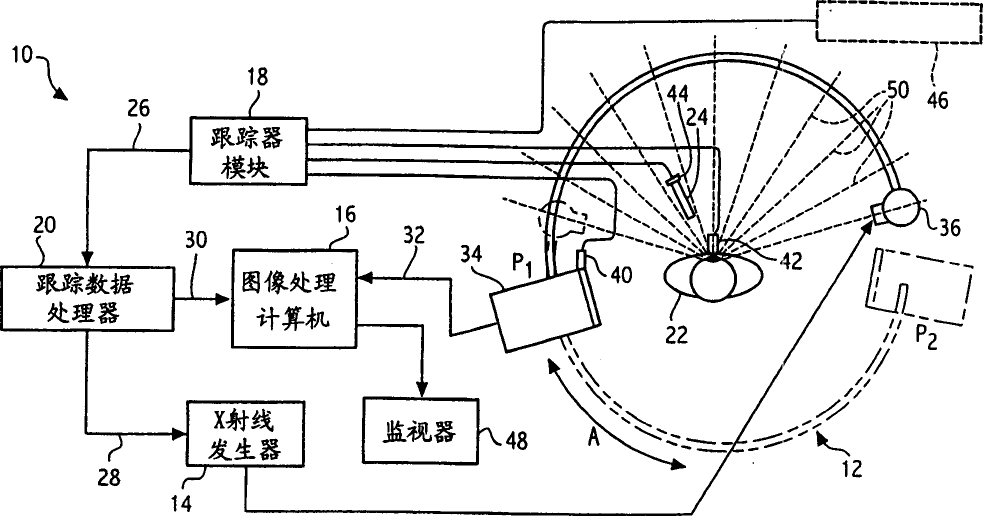
[0027] figure 1 A fluoroscopy x-ray system 10 is shown comprising a C-arm 12 electrically connected to an x-ray generator 14 , an image processing computer 16 and a tracker module 18 . Tracker module 18 is in communication with tracking data processor 20 , which in turn is in communication with image processing computer 16 and x-ray generator 14 . Image processing computer 16 is in communication with monitor 48 .

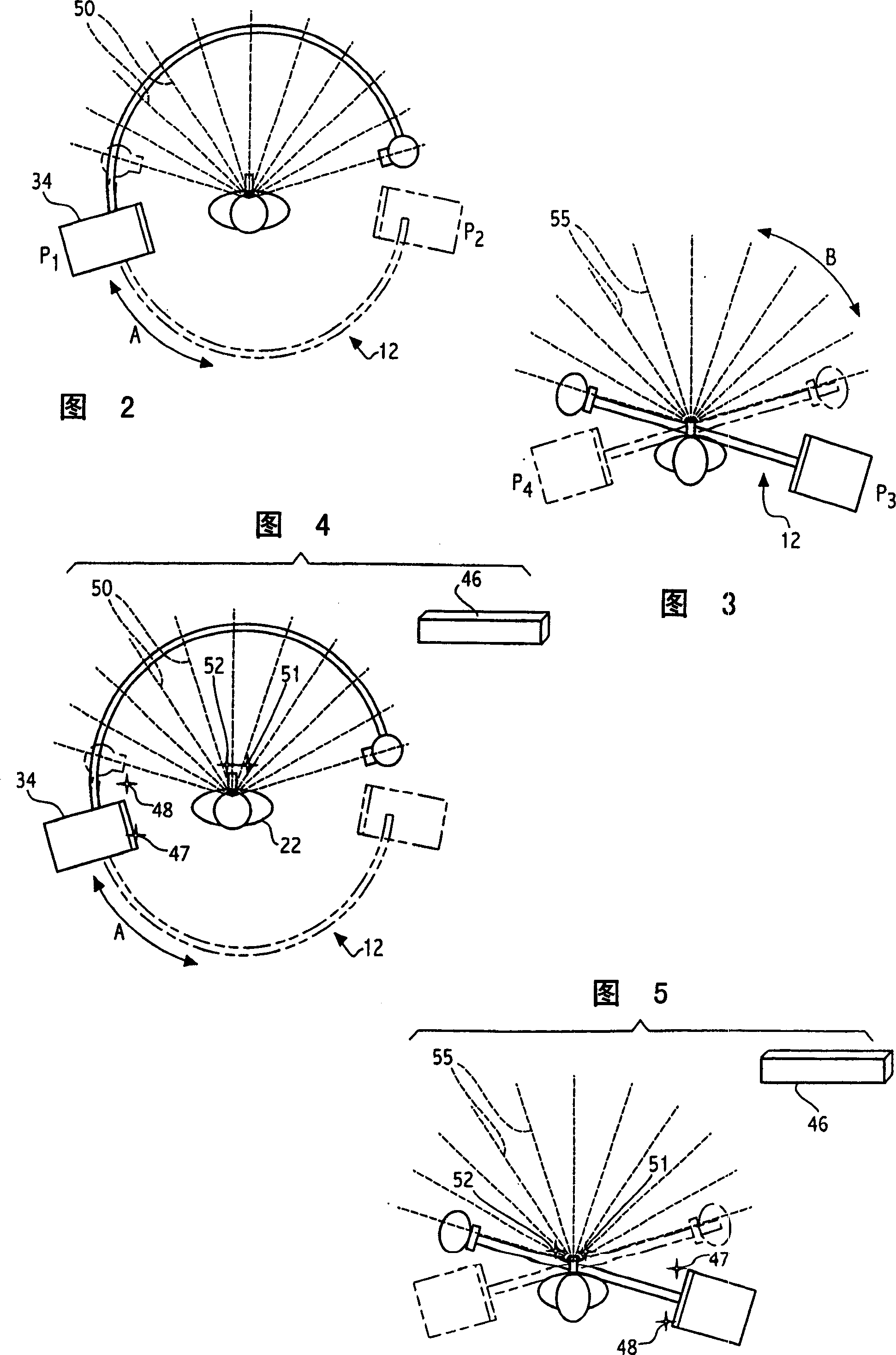
[0028] The C-arm 12 includes an x-ray source 36 mounted on one side and an x-ray receiver arrangement 34 mounted on the opposite side. The C-arm 12 is movable in several directions along multiple image acquisition paths, including an orbital tracking direction, a longitudinal tracking direction, a lateral tracking direction, a lateral tracking direction, a pivot tracking direction, and a "swing" tracking direction. The direction of orbital rotation is shown by arrow A. figure 1 The C-arm 12 and receiver 34 are shown in solid lines in a first position ( P1 ) and...


PUM


Abstract

A medical imaging system is provided for diagnostic and interventional procedures. The system includes a C-arm having an x-ray source and a receptor for obtaining fluoroscopic images of a patient. The C-arm is moved through an image acquisition path (A, B), along which at least first and second images are obtained. An acquisition module obtains multiple 2-D fluoroscopic images at desired positions along the image acquisition path and an image processor constructs a 3-D volume of object data based on the 2-D fluoroscopic images. Patient information is displayed based upon the 3-D volume of patient information. A position tracking system is included to track the position of the receptor, patient and (if included) a surgical instrument. The position information is used to control the time at which exposures are obtained and (if included) to superimpose instrument graphical information on a display with patient information.

Description

Background of the invention [0001] Preferred embodiments of the present invention generally relate to x-ray systems based on a mobile C-arm for constructing three-dimensional (3-D) volumetric data sets and using the data in diagnostic and interventional medical procedures set. More specifically, at least one preferred embodiment of the present invention relates to an x-ray medical imaging system based on a mobile C-arm that processes a three-dimensional volumetric data set of digital x-ray images based in part on patient and x-ray receiver coordinate information. Construct and use this data set for the diagnostic and interventional procedures to be performed. [0002] Conventional medical imaging equipment, such as computed tomography (CT) and magnetic resonance imaging (MRI), use complex mechanical gantry structures to support the patient and the devices used to construct patient imaging datasets. CT and MRI data sets are formed from multiple scans in which the exact positi...

Claims


Application Information

Patent Timeline
IPC IPC(8): A61B5/06A61B6/00A61B6/03A61B19/00
CPCA61B6/463A61B6/547A61B6/4441A61B6/466A61B2562/043A61B6/4405A61B2505/05A61B5/1114A61B5/06A61B19/52A61B90/36A61B5/062
Inventor V·T·詹森
Owner GE MEDICAL SYST GLOBAL TECH CO LLC
Why Eureka
Try Eureka