Jaw crusher

A jaw crusher and clamping mechanism technology, applied in grain processing and other directions, can solve the problems of taking a long time, covering a large area, and increasing the price.

Inactive Publication Date: 2003-04-02
KOMATSU LTD
View PDF2 Cites 18 Cited by
  • Summary
  • Abstract
  • Description
  • Claims
  • Application Information

AI Technical Summary

Problems solved by technology

Therefore, the toggle plate 67 is clamped. In order to maintain this situation, springs 68 and 85 are provided, so the structure is complicated. Every time the gap between the teeth is adjusted, the springs 68 and 85 must be adjusted, and the adjustment time becomes longer.
In addition, when it is mounted on a vehicle, the work space is narrowed, so adjustment work becomes difficult
[0010] In addition, an adjustment cylinder 71 is provided at the rear end of the cylinder 70. Therefore, the overall length of these cylinders becomes longer and they are arranged laterally. Therefore, Figure 8 The overall length N of the movable jaw 61 shown becomes longer, and the occupied area is large, which is inconvenient to carry
Also, since the adjustment cylinder 71 is constantly pressurized, energy is consumed
Also, there are oil leaks and it's unreliable
In order to prevent this oil leakage, it is necessary to configure a complicat

Method used


Image

  • Jaw crusher
  • Jaw crusher
  • Jaw crusher

Examples


Embodiment Construction

[0036] Preferred embodiments of the jaw crusher of the present invention will be described in detail below with reference to the accompanying drawings.

[0037] First, based on Figure 1 to Figure 6 The first embodiment will be described.

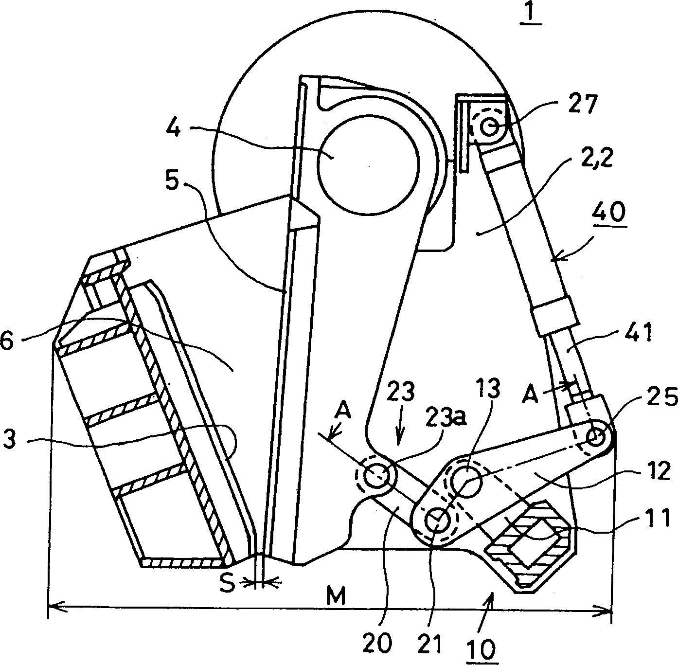
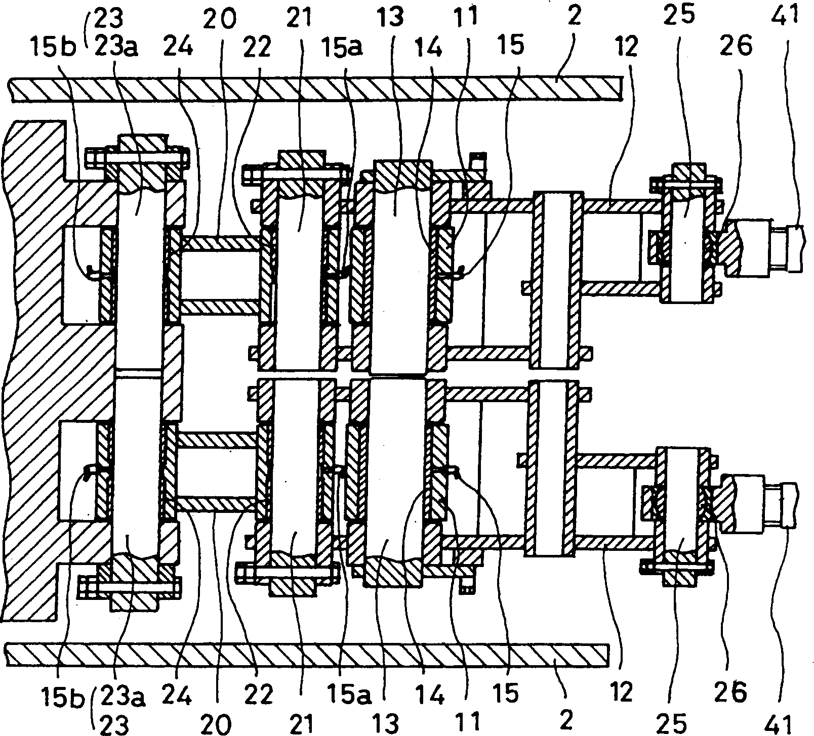
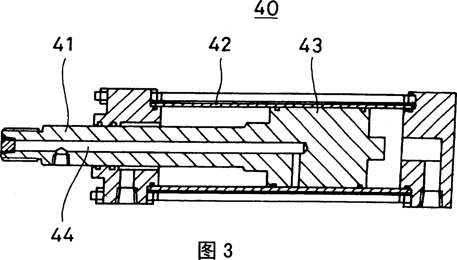
[0038] figure 1 It is a partial side sectional view showing an example of the jaw crusher 1 . exist figure 1 Among them, a fixed tooth 3 is installed between a pair of left and right fixed cones 2, 2, and at a position facing the fixed teeth 3, the movable tooth 5 swings and hangs freely on the eccentric drive shaft 4 set on the fixed cones 2, 2 Above, a crushing chamber 6 is formed between the fixed teeth 3 and the movable teeth 5 . On the back side of the movable tooth 5 between the fixed cones 2 and 2, a movable tooth bearing portion 10 forming a link mechanism is provided. That is, on the bracket 11 fixedly installed on the fixed cones 2 , 2 , the intermediate portion in the longitudinal direction of the lever 12 is swingably att...


PUM


Abstract

A compact and light-weight jaw crusher, in which life span of parts enduring abrasion is long, and an outlet clearance of a crushing chamber is easily adjusted, is provided. For this purpose, the jaw crusher includes a stationary jaw (3) fixedly provided at a frame (2), a movable jaw (5) which is provided to oppose the stationary jaw and attached swingably with an eccentric drive shaft (4), a movable jaw load receiving section (10) attached to the frame, and a coupling joint (23) which is a connecting member for connecting a lower portion of the movable jaw and the movable jaw load receiving section and swingably connects the lower portion of the movable jaw and the movable jaw load receiving section.

Description

technical field [0001] The invention relates to a jaw crusher, in particular to a movable tooth holding mechanism and a gap adjustment mechanism between the movable tooth and the fixed tooth. Background technique [0002] There have been various proposals regarding the structure of jaw crushers. For example, there are jaw crushers disclosed in JP-A-5-45300 and JP-A-10-249224. [0003] Figure 8 It is an explanatory diagram of a side section of a crusher disclosed in Japanese Patent Publication No. 5-45300. Inside the crusher frame 60 , the movable jaw 61 having the movable teeth 5 is hung and installed on the eccentric shaft 62 , and the fixed teeth 3 are mounted opposite to it. The lower end of the toggle 63 is freely rotatably mounted on the frame 60 of the crusher by a pin shaft 64 . On the frame 60 of the crusher, the base end of the oil cylinder 70 with the friction force clamped between the sleeve and the piston rod is installed freely to swing, and its front end is ...

Claims


Application Information

Patent Timeline
IPC IPC(8): B02C1/00B02C1/02B02C1/04B02C13/09
CPCB02C1/025B02C1/04B02C1/005B02C1/02B02C13/00B02C13/09
Inventor 富樫良一山田光伸
Owner KOMATSU LTD
Why Eureka
Try Eureka