Heat exchanger

A technology for heat exchangers and cluster tubes, which is applied in heat exchange equipment, indirect heat exchangers, heat exchanger shells, etc., can solve problems such as the unsuitability of carbon dioxide heat exchangers

Inactive Publication Date: 2003-04-16
HANON SYST
View PDF6 Cites 46 Cited by
  • Summary
  • Abstract
  • Description
  • Claims
  • Application Information

AI Technical Summary

Problems solved by technology

However, the heat exchanger basically uses a multi-pass method, which is not suitable for carbon dioxide heat exchangers

Method used


Image

  • Heat exchanger
  • Heat exchanger
  • Heat exchanger

Examples


Embodiment Construction

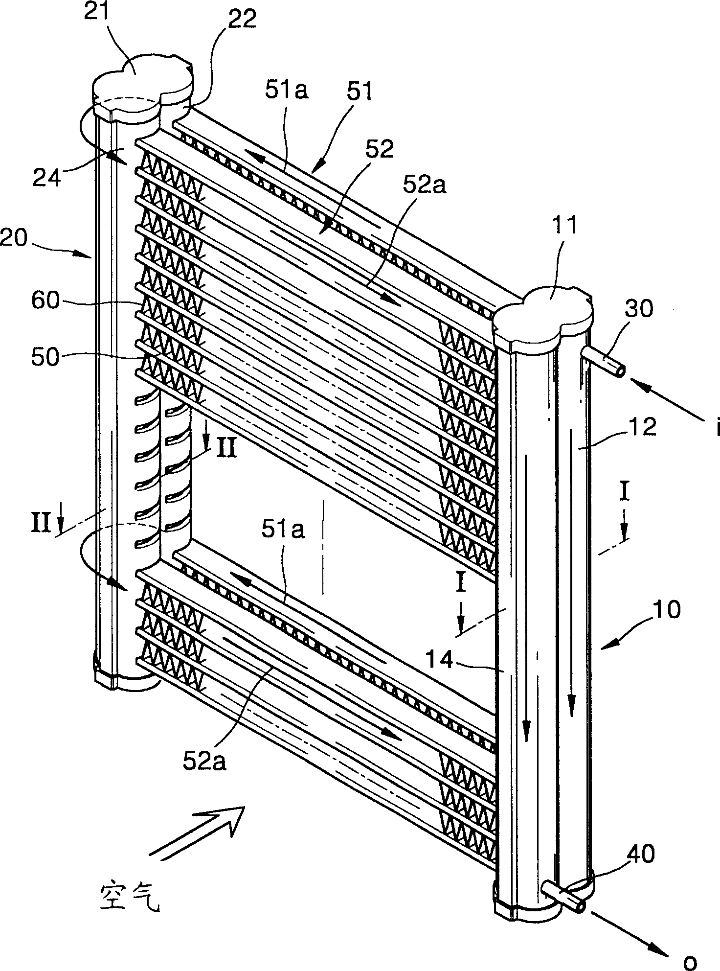
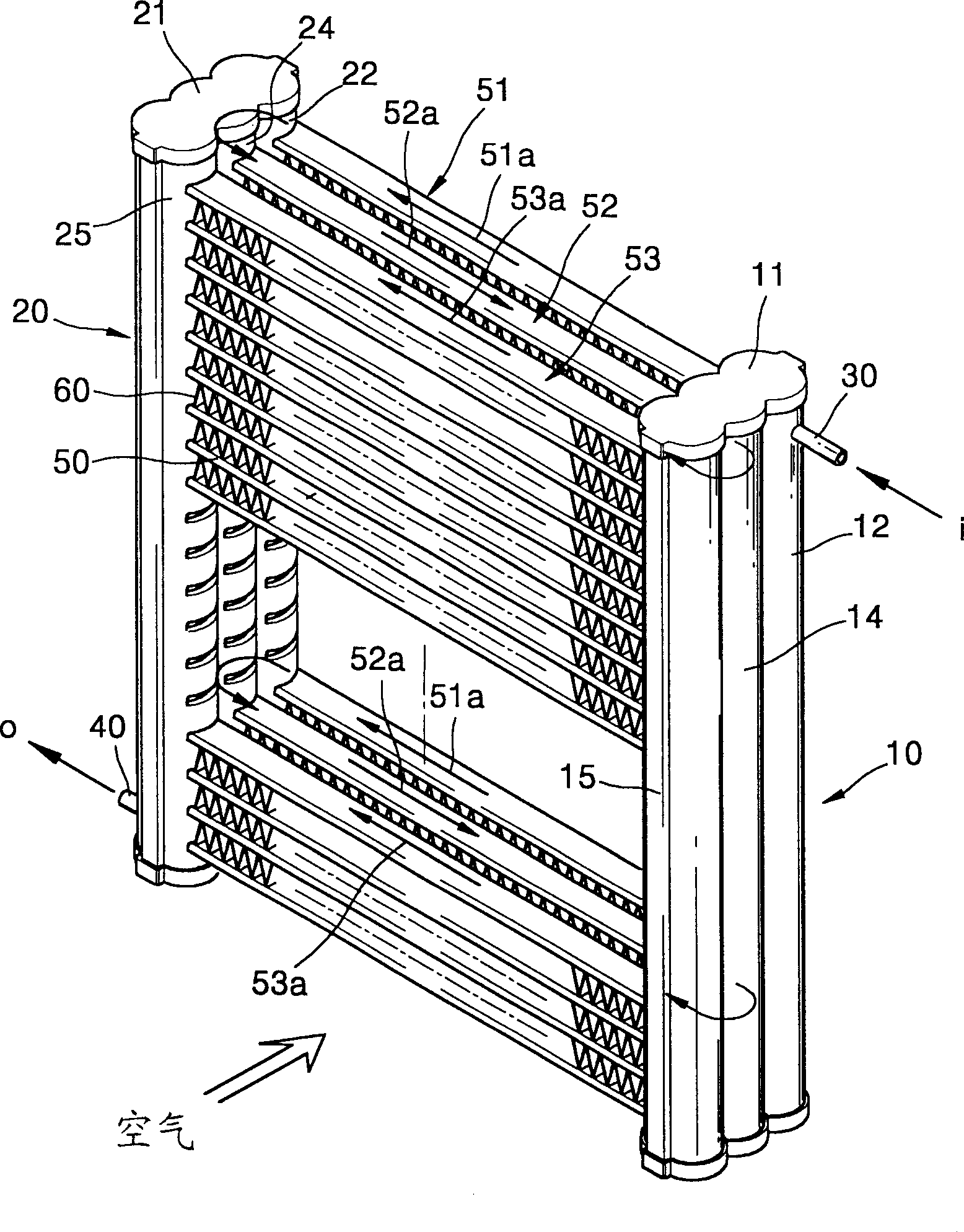
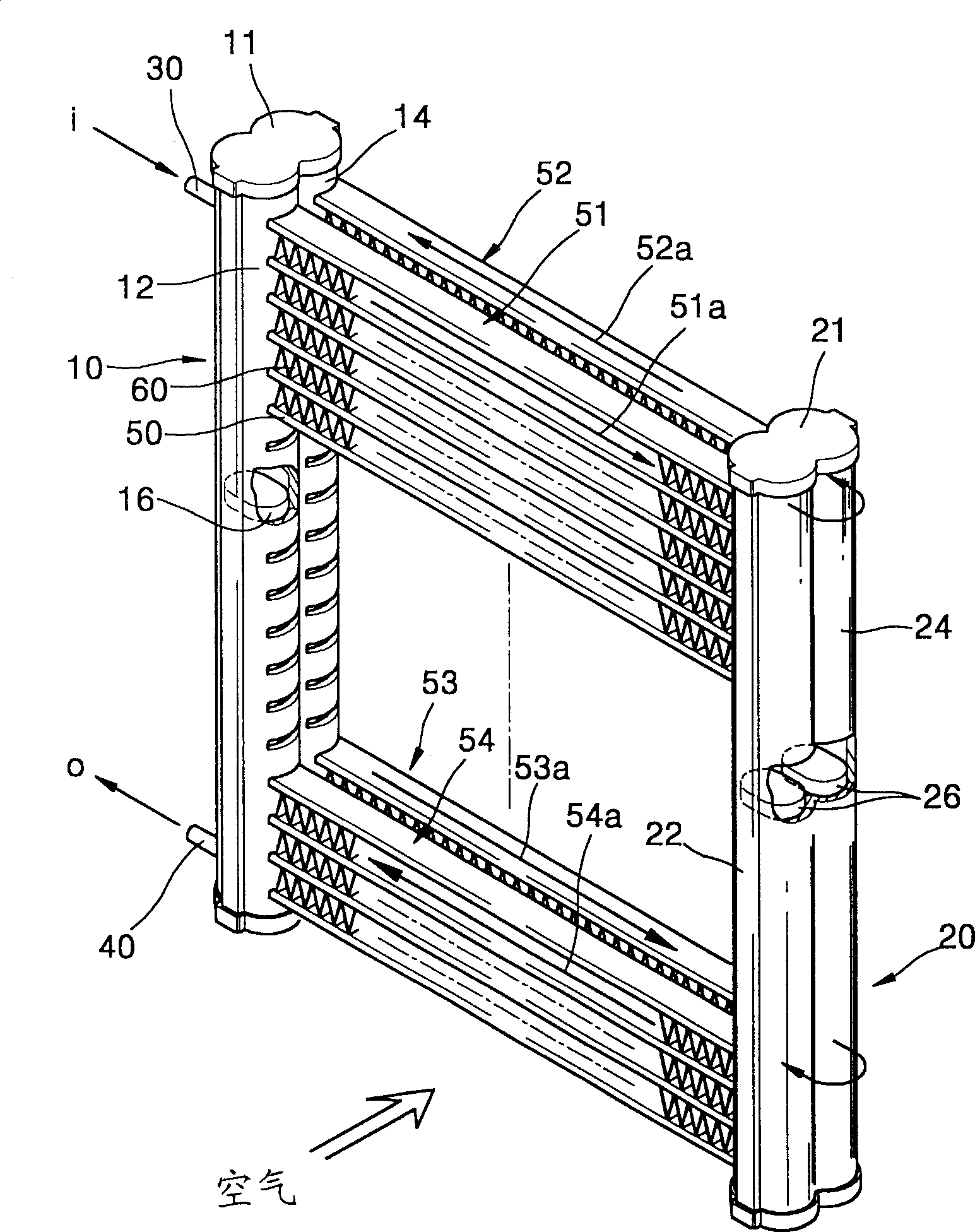
[0068] See attached figure 1 , the heat exchanger of a preferred embodiment of the present invention comprises: a first bundle tube 10 and a second bundle tube 20, the first bundle tube has a first chamber 12 and a third chamber 14, the two The chambers are separated by a partition, and the second manifold has a second chamber 22 and a fourth chamber 24, which are separated by a partition. The upper and lower ends of each of the bundled tubes 10 and 20 are sealed by caps 11 and 21, and the bundled tubes 10 and 20 are spaced apart from each other by a predetermined distance and parallel to each other.

[0069] A set of tubes 50 connecting the respective chambers 12 , 14 , 22 and 24 and through which refrigerant flows is installed between the first and second bundled tubes 10 and 20 . The tube 50 connects the first chamber 12 of the first tube bundle 10 and the second chamber 22 of the second tube bundle 20 , and the third chamber 14 of the first tube bundle 10 and the fourth c...


PUM


Abstract

A heat exchanger uses a refrigerant acting under a high pressure, such as carbon dioxide, as a refrigerant. The heat exchanger includes first (10) and second (20) header pipes arranged a predetermined distance from each other and parallel to each other, each having at least two chambers (12,14,22,24) independently sectioned by a partition wall, a plurality of tubes (50) for separately connecting the chambers of the first (10) and second (20) header pipes, facing each other, wherein the tubes (50) are divided into at least two tube groups (51,52), each having a single refrigerant path, a refrigerant inlet pipe (30) formed at the chamber disposed at one end portion of the first header pipe (10), through which the refrigerant is supplied, a plurality of return holes (29) formed in the partition wall to connect two chambers adjacent to each other, through which the refrigerant sequentially flows the tube groups (51,52), and a refrigerant outlet pipe (40) formed at the chamber of one of the first and second header pipes connected to a final tube group of the tube groups along the flow of the refrigerant, through which the refrigerant is exhausted.

Description

technical field [0001] The invention relates to a heat exchanger, in particular to a heat exchanger using carbon dioxide as a refrigerant. Background technique [0002] Generally, a heat exchanger is a heat exchange device that transfers heat from a high temperature fluid to a low temperature fluid through a wall surface. Freon-based refrigerants are currently mostly used as refrigerants for air-conditioning systems having a heat exchanger. However, since freon-based refrigerants are considered to be a major cause of global warming, their use has gradually been limited. Under the above-mentioned circumstances, various research works on carbon dioxide as a next-generation refrigerant replacing freon-based refrigerants are being actively carried out. [0003] The global warming potential (GWP) of carbon dioxide is only about 1 / 1300 of that of R134a, which is a typical freon-based refrigerant, so carbon dioxide is considered as an environmentally friendly refrigerant. In add...

Claims


Application Information

Patent Timeline
Patent Type & Authority Applications(China)
IPC IPC(8): F25B9/00F25B39/00F25B39/02F28D1/04F28D1/053F28F1/02F28F9/02F28F9/26
CPCF25B39/02F28F2225/08F28D1/05391F28F2210/04F28D1/0417F28F9/262F25B9/008F28D2021/0073F28F9/0224F28F9/0214F28D1/0435F28F1/022F28D2021/0085
Inventor 李俊康张吉相韩寅铁朴昌镐安龙贵安黄载
Owner HANON SYST
Why Eureka
Try Eureka