Check patentability & draft patents in minutes with Patsnap Eureka AI!

Synchronous rectification in flyback converter

A technology of inverse converters and capacitors, which is applied to conversion equipment with intermediate conversion to AC, conversion of DC power input to DC power output, instruments, etc., can solve problems such as incorrect timing of secondary side switches, and achieve simple application delay Effect

Inactive Publication Date: 2003-05-07
UNWIRED PLANET
View PDF3 Cites 4 Cited by
  • Summary
  • Abstract
  • Description
  • Claims
  • Application Information

AI Technical Summary

Problems solved by technology

The disadvantage of this circuit is that under some conditions the timing of the secondary switch may not be correct

Method used


Image

  • Synchronous rectification in flyback converter
  • Synchronous rectification in flyback converter
  • Synchronous rectification in flyback converter

Examples


Embodiment Construction

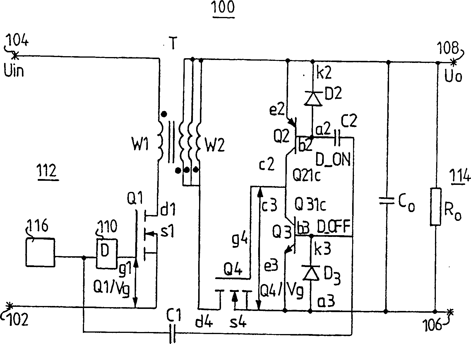
[0039] figure 1 A circuit diagram of the flyback converter 100 is shown in . On the primary side 112 , the converter 100 includes a primary side winding W1 belonging to the transformer T, a main switch Q1 , a control device 116 , and a delay circuit 110 . The first input terminal 104 of the primary side 112 is connected to one side of the primary side winding W1 for connection to one terminal of a DC voltage source, not shown, when the converter is used. The other change of the primary winding W1 is connected to the drain terminal d1 or similar connection point of the main switch Q1, for example, Q1 may be a MOSFET transistor. The source terminal s1 or the like of the main switch Q1 is connected to the second input terminal 102 of the primary side 112, which when using the converter is connected to the other terminal of the aforementioned external DC voltage source. The output terminal of the control device 116 is connected to the first capacitor terminal of the first drive ...


PUM


Abstract

A flyback converter (100) has a primary side (112) comprising a main switch (Q1) and a control device (116) and a delay circuit (110). The converter has a secondary side (114) comprising a drive circuit controlling a rectifying switch (Q4). The drive circuit comprises a first part including a first transistor (Q2), a first discharge diode (D2) and an on-node (D_ON) and a second part including a second transistor (Q3), a second discharge diode (D3) and an off-node (D_OFF). The control device is connected to the drive circuit via at least one drive capacitor (C1, C2) to the on- and off-nodes. The drive circuit has a first mode of operation in a flyback phase and a second mode of operation is a forward phase. The flyback converter comprises few components and the main switch is efficiently prevented from conducting simultaneously with the rectifying switch.

Description

technical field [0001] The present invention relates to a DC-DC converter circuit, and more particularly to a synchronous flyback converter circuit operating in a continuous mode. Background technique [0002] In the DC-DC power supply of various electrical equipment, in order to obtain a suitable rectified output voltage, a power rectifier is used. Typically, a diode is used on the secondary side to obtain the rectified output voltage. [0003] A DC-DC converter is described in US Patent No. 5,886,881 to Xia et al. The described forward DC-DC converter can be used to perform synchronous rectification and zero voltage switching. This circuit is only designed for forward or forward derived converters and cannot be used for flyback converters. [0004] Another DC-DC converter is described in US Patent No. 5,726,869 to Yamashita et al. A synchronous rectification type forward DC-DC converter is disclosed, which can prevent the loss that occurs when the synchronous rectifica...

Claims


Application Information

Patent Timeline
IPC IPC(8): H02M3/28H02M3/335
CPCY02B70/1475H02M3/33592Y02B70/10
Inventor B·赫登斯科A·斯文松
Owner UNWIRED PLANET
Features
  • R&D
  • Intellectual Property
  • Life Sciences
  • Materials
  • Tech Scout
  • Unparalleled Data Quality
  • Higher Quality Content
  • 60% Fewer Hallucinations
Learn More