

Optical fibre electric field sensor
A fiber optic electric field and sensor technology, applied in electrostatic field measurement, voltage/current isolation, etc., can solve the problems of low sensor stability and reliability, low production efficiency, easy to generate displacement, etc., to solve the problem of structural stability. Effect
Inactive Publication Date: 2003-05-21
HUAZHONG UNIV OF SCI & TECH
View PDF0 Cites 21 Cited by
- Summary
- Abstract
- Description
- Claims
- Application Information
AI Technical Summary
Problems solved by technology
This structure has obvious disadvantages: 1. Due to no positioning measures, the optical components are not fixed, and displacement is easy to occur; 2. Since the connection between the lens and the end face of the polarizer is suspended, the structure is unstable, and displacement is easily generated, even Falling off leads to a change in the coupling efficiency between the input lens and the output lens, or even no coupling; 3. Because the structure is not fixed, the bonding is random, and the bonding is often uneven, and the front and rear are misaligned. It is also difficult to make an ideal sensor with a five-dimensional fine-tuning instrument, and it is time-consuming
In short, the stability and reliability of the sensor with the above structure are not high, the processing technology is difficult, the production efficiency is low, and the dispersion is large.
Method used
View moreImage
Smart ImageViewing Examples

Examples
Embodiment Construction
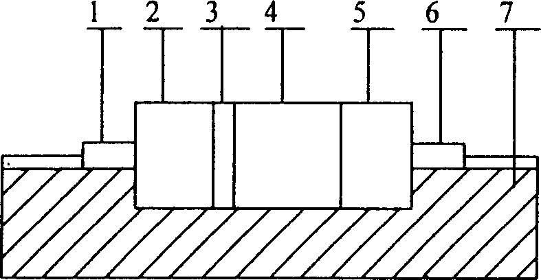
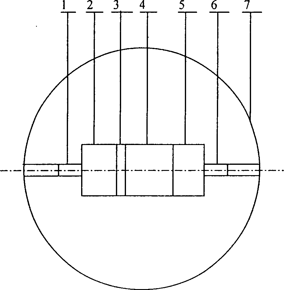
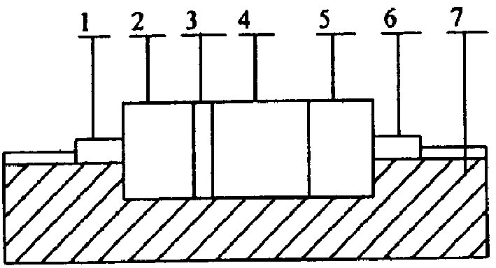
[0010] Such as Figure 1 and Figure 2 As shown, the collimator lens 1, the polarizer 2, the λ / 4 wave plate 3, the electro-optic crystal 4, the analyzer 5, and the coupling lens 6 are sequentially placed in the groove of the plexiglass substrate 7, and glued with optical glue. Put the upper half of the plexiglass substrate, and stick the upper and lower parts firmly to make the optical fiber electric field sensor.
Login to View More PUM
 Abstract
The invention is a fiber-optical electric-field sensor namely a photoelectric measuring device, based on electrooptic effecct to measure electric field, including collimation lens, polarizer, lambda / 4 wave piece, electrooptic crystal, polarization detector and coupler lens in order placed in light path. Each optical cell is inserted on organic glass basic body with the flute matching the shape and order of the optical cells, and the optical cells are felted one another and the cells and the glass are also felted by optical glue. The link and test of light-path system is convenient.
Description
technical field [0001] The invention belongs to a photoelectric measuring device, which measures the electric field based on the electro-optic effect. Background technique [0002] The measurement of electric field based on the Pockels electro-optic effect principle has been reported in the literature, see Yan Yongzhi, Wang Dehe, Gao Xicai, etc., Optical fiber voltage and electric field sensor using bismuth germanate electro-optic effect, Piezoelectricity and Acousto-optic, 1986.2, first issue, p.p23 -27; Yang Xiaochun, Yan Yongzhi, Theoretical Analysis and Design of Winkels Components for Optical Fiber Electric Field Sensor, Piezoelectricity and Acousto-Optics, 1986.4, No.2, p.p13-18, this sensor is mainly composed of collimating lens, Polarizer, λ / 4 wave plate, electro-optic crystal, analyzer and coupling lens. The process is: the light emitted by the LED is transmitted to the electric field sensor through the optical fiber, coupled into the polarizer by the collimator le...
Claims
Login to View More Application Information
Patent Timeline
 IPC IPC(8): G01R15/24G01R29/12
Inventor李开成张健梅戴建华
OwnerHUAZHONG UNIV OF SCI & TECH