Method for inserting images on printing plates

An imaging and printing plate technology, applied in the field of printing plate imaging, can solve the problem of difficult silicone resin layer processing and other problems

Inactive Publication Date: 2003-06-04
KOENIG & BAUER AG
View PDF3 Cites 9 Cited by
  • Summary
  • Abstract
  • Description
  • Claims
  • Application Information

AI Technical Summary

Problems solved by technology

But it is difficult to handle the silicone layer to be sprayed

Method used


Image

  • Method for inserting images on printing plates
  • Method for inserting images on printing plates
  • Method for inserting images on printing plates

Examples


Embodiment Construction

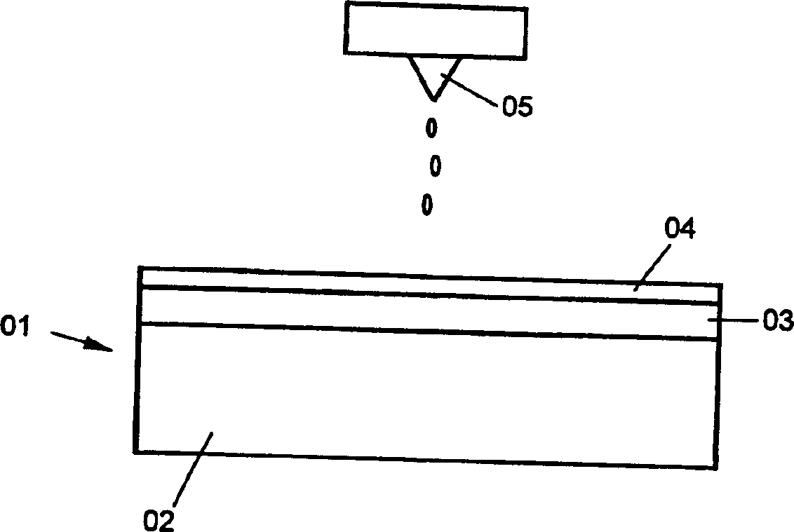
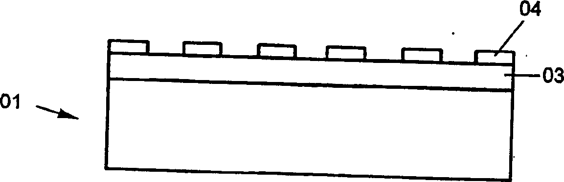
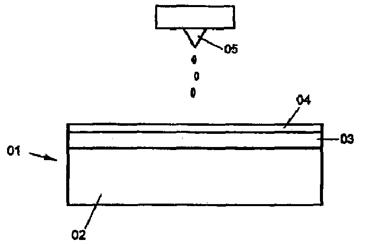
[0019] figure 1 The printing plate 01 shown has a carrier layer or matrix 02, which is composed of aluminum and has a corresponding thickness in order to achieve the desired properties. An ink layer 03 and an ink repellent layer 04 are coated on the substrate. The ink layer 03 may be a polyethylene film. Its thickness is in the range of 5-50 μm, preferably 20 μm. The ink repellent layer 04 is made of silicone resin. The thickness can be selected accordingly. Its thickness can be in the range of several μm. In this embodiment, it is 2 μm. There can be an adhesive-or bottom layer between the substrate 02 and the ink layer 03. In this embodiment, this layer is a titanium oxide layer.

[0020] Preferably, a watermarkless version produced by Presstek (trade name: PearlDry) is used, and the structure of the printing plate is clearly disclosed in US 54 87 338A.

[0021] In order to realize the dissolution and removal of the silicone resin layer in the corresponding segment of the image...


PUM


Abstract

The invention concerns a method for inserting images on printing plates, wherein a printing plate is prepared with an ink-accepting layer and an ink-repelling layer applied thereon. According to the invention, a developing fluid is sprayed on the ink-repelling layer by an ink-jet printing group in accordance with an image to be printed, by means of which the ink-repelling layer is etched or dissolved in the sprayed areas for swelling or adhesion promotion is eliminated. The etched or dissolved areas of the ink-repelling layer are removed. A waterless printing plate having an ink-repelling layer made of silicon is especially used.

Description

Technical field [0001] The invention relates to a method for imaging printing plates according to the preamble of claim 1. Background technique [0002] Various methods for imaging flat or printing plates for offset printing are known. On the one hand, the photosensitive plate is exposed with a laser and then subjected to wet chemical development. There is also a so-called hot plate according to the prior art, in which the uppermost layer can be complexed by laser and the subsequent process is completed in the next step. Another option is used when using the so-called thermal etch version. Here, the absorbed intermediate layer is evaporated by a laser, and then the ink repellent layer on it is dissolved and removed in the next step (see: US 54 87 338A). [0003] It is also known to image printing plates by applying a corresponding liquid. According to US 40 03 312A, a silicone resin solution is sprayed on the printing plate substrate according to the image to be printed and harde...

Claims


Application Information

Patent Timeline
Patent Type & Authority Applications(China)
IPC IPC(8): B41J2/01B41C1/10B41N1/14
CPCB41C1/1066B41C1/1008B41C2210/16
Inventor 卡尔·埃里希·阿尔伯特·沙舍克格奥尔格·施奈德
Owner KOENIG & BAUER AG
Why Eureka
Try Eureka