Bidirectional channel restitution in automatic optical exchange network
A two-way channel and recovery method technology, applied in the field of two-way channel recovery, can solve problems such as slow recovery speed, lack of consideration of parallelism, complex recovery conditions, etc., and achieve the effects of simple operation, accelerated recovery process, and shortened recovery time
- Summary
- Abstract
- Description
- Claims
- Application Information
AI Technical Summary
Problems solved by technology
Method used
Image

Examples
Embodiment 1
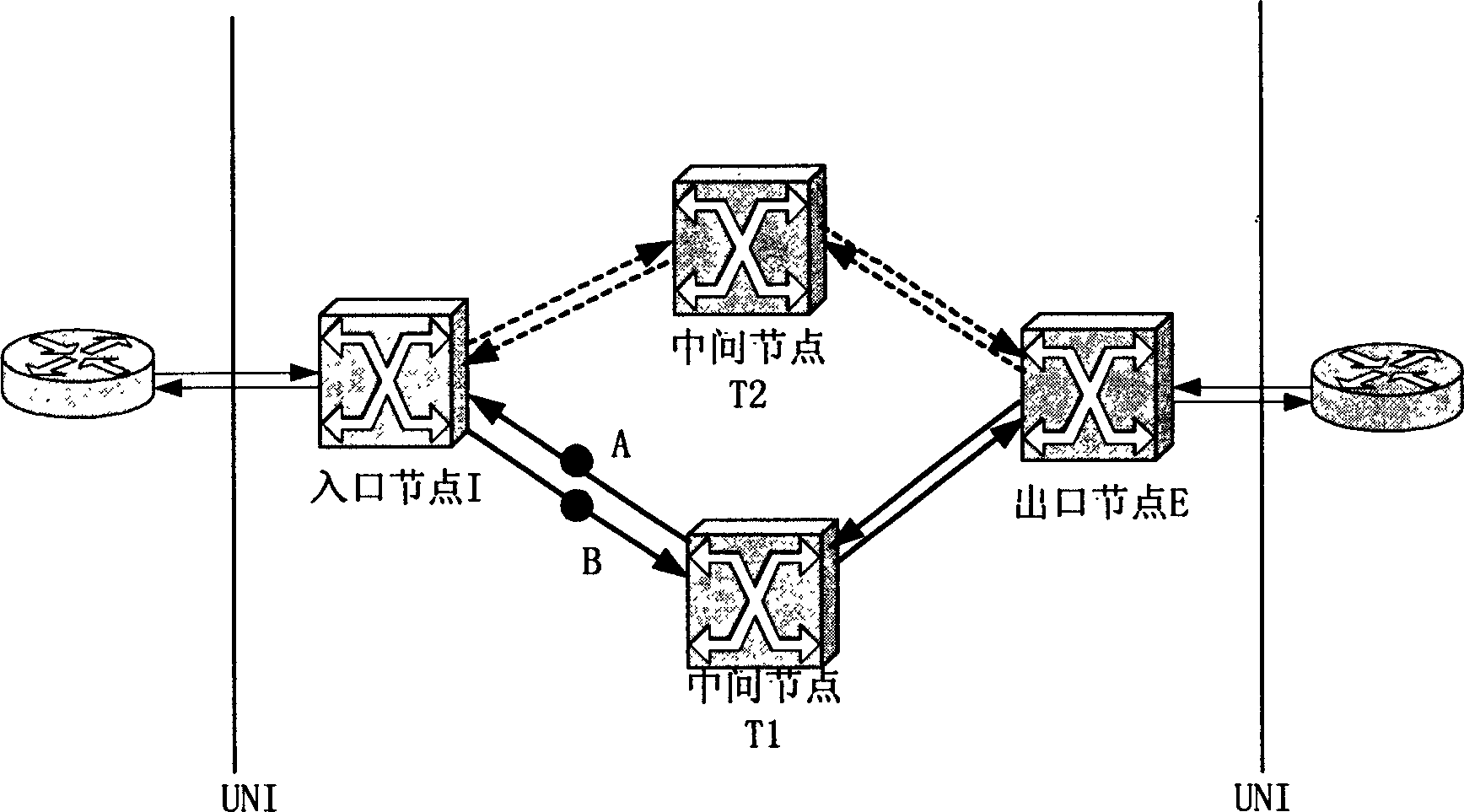
[0026] exist figure 2 In the network environment shown, there are bidirectional optical channels: (I, T1, E). Now assume that the link from I to T1 fails, that is, point B fails. T1 and E detect loss of optical signal. The actions of each node are as follows:
[0027] Because T1 is an intermediate node, there is no action.
[0028] E is the egress node, so I is notified of the failure, and the cross-connect is removed.
[0029] Ingress node I first receives the fault notification, and the subsequent operations are as follows:
[0030] 1) Routing calculation, while releasing the cross-connection.
[0031] 2) Assuming that the calculated new path is (I, T2, E), after the cross-connection is released, the signaling process of path construction starts (sending a path construction request to T2).
[0032] 3) After the road construction is completed (the road construction response is received), the signaling process of road tearing down is started (the road tearing down reque...
Embodiment 2
[0036] exist figure 2 In the network environment shown, there are bidirectional optical channels: (I, T1, E). Now assume that the link from T1 to I fails, that is, point A fails. I detected loss of optical signal. The actions of each node are as follows:
[0037] Ingress node I first finds that the optical signal is lost, and the subsequent operations are as follows:
[0038] 1) Routing calculation, while releasing the cross-connection.
[0039] 2) Assuming that the calculated new path is (I, T2, E), after the cross-connection is released, the signaling process of path construction starts (sending a path construction request to T2).
[0040] 3) After the road construction is completed (the road construction response is received) and the fault notification from E is received, the signaling process of the road tearing down is started (the road tearing down request is sent to T1).
[0041] 4) The path removal is completed (the path removal response is received), and the res...
Embodiment 3
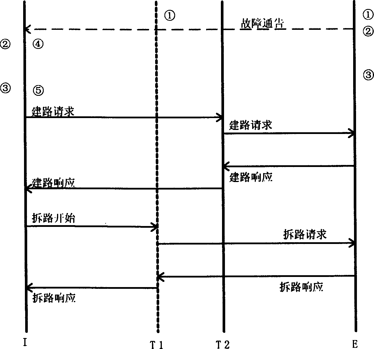
[0045] exist figure 2 In the network environment shown, there are bidirectional optical channels: (I, T1, E). Now assume that the links between T1 and I both fail, that is, the two points A and B fail. The actions of each node are the same as in Embodiment 2, except that in Embodiment 2: T1 and E find that the optical signal is lost because I cancels the cross-connection. However, in Embodiment 3: T1 and E find that the cause of the optical signal loss is a link failure. The whole process is as Figure 5 .
PUM
 Abstract
Description
Claims
Application Information
 - R&D
- Intellectual Property
- Life Sciences
- Materials
- Tech Scout
- Unparalleled Data Quality
- Higher Quality Content
- 60% Fewer Hallucinations
Browse by: Latest US Patents, China's latest patents, Technical Efficacy Thesaurus, Application Domain, Technology Topic, Popular Technical Reports.
© 2025 PatSnap. All rights reserved.Legal|Privacy policy|Modern Slavery Act Transparency Statement|Sitemap|About US| Contact US: help@patsnap.com