Rolling bearing component

A technology for rolling bearings and components, applied in the field of thin-walled rolling bearing components, can solve problems such as expensiveness, accuracy, cracks, etc. that affect the overall size and shape

Inactive Publication Date: 2003-06-25
SCHAEFFLER TECH AG & CO KG
View PDF2 Cites 10 Cited by
  • Summary
  • Abstract
  • Description
  • Claims
  • Application Information

AI Technical Summary

Problems solved by technology

But this induction annealing process is laborious and therefore expensive, and affec

Method used


Image

  • Rolling bearing component
  • Rolling bearing component

Examples


Embodiment Construction

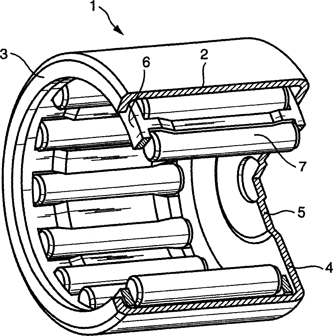
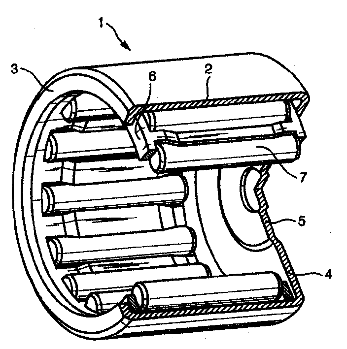
[0046] The needle roller bushing shown in the drawing and marked with 1 has a radial section 2 of circular ring contour, one end of which is bent into a radially inward rim 3 and the other end is closed with a base plate 4 . Needle rollers 7 in a cage 6 are placed rolling between the base plate 4 provided with the bulge 5 and the rim 3 . Such a needle roller bushing 1 surrounds the bearing point of the shaft end.

[0047]The needle roller sleeve 1 is formed by a high-quality steel cold-rolled strip with a thickness of 1.2mm and the following chemical composition through multiple processing steps: 0.40%C, 0.10%Si, 0.5%Mn, 0.10%Mo, 0.3%Cr , 0.01% P, 0.005% S, 0.1% Cu, 0.1% Ni, 0.005% Sn, 0.002% Sb, wherein the sum of Cu, Ni, Mn and Cr is 1.02%. In addition, fine-grain stabilizing elements such as aluminium, titanium and niobium can be present in a total composition of 0.06%. The cage 6 is made of carburized steel marked St3, and the needle roller 7 is made of hardened steel ma...


PUM


Abstract

Thin walled roller bearing component is produced from a cold strip made from a tempered steel having a tensile strength of not more than 480 N/mm 2>, a breaking elongation of at least 24%, an apparent yielding point of not more than 380 N/mm 2> and an anisotropic value R of 0.85-1.05 with delta Rmax = 0.3 mm. The cold worked roller bearing component has a surface hardness of at least 700 HV and a core hardness of no more than 650 HV.

Description

technical field [0001] The invention relates to a chip-free thin-walled rolling bearing component, such as a rolling bearing ring, a pin bushing or a needle bushing, produced from cold-rolled strip. Background technique [0002] Cold-rolled strip is often used to manufacture cold-worked products. Due to the increased requirements for application and use characteristics, better mechanical characteristics, especially molding characteristics, are required. Good formability is characterized by the highest possible r-values ​​for deep-drawability, high n-values ​​for stretchability and high elongation values ​​for planar elongational deformation properties. In this case it has proven to be advantageous if the shaping properties in the different directions, in particular in the longitudinal, transverse and diagonal directions, are as uniform as possible, ie largely isotropic. The advantage of the isotropic behavior is an essentially uniform flow of the substance and a reduction ...

Claims


Application Information

Patent Timeline
IPC IPC(8): F16C33/46C21D1/06C21D8/04C21D9/14C21D9/40C22C38/00C22C38/04C22C38/42C22C38/44C22C38/50C22C38/60C23C8/22C23C8/26F16C19/46F16C21/00F16C33/30F16C33/62F16C33/64
CPCF16C19/46C21D9/40C21D9/14C22C38/04C22C38/60C22C38/44Y10S384/912F16C33/54F16C33/30F16C33/64C22C38/42F16C21/005F16C2202/04C22C38/008C21D2221/10F16C33/588F16C33/62C21D8/0436F16C33/546F16C19/466F16C2300/02
Inventor 卡尔-路德维希·格雷尔京特·格鲁贝利奥·明特尼希
Owner SCHAEFFLER TECH AG & CO KG
Why Eureka
Try Eureka