Vortex compressor

A scroll compressor and casing technology, applied in the field of compressors, can solve the problems of high cost, achieve the effects of reducing manufacturing costs, reducing processing, and preventing reversal

Inactive Publication Date: 2003-07-02
LG ELECTRONICS (TIANJIN) APPLIANCES CO LTD
View PDF0 Cites 3 Cited by
  • Summary
  • Abstract
  • Description
  • Claims
  • Application Information

AI Technical Summary

Problems solved by technology

All in all, a lot of processing and assembly processes are required, and the cost is high

Method used


Image

  • Vortex compressor
  • Vortex compressor
  • Vortex compressor

Examples


Embodiment Construction

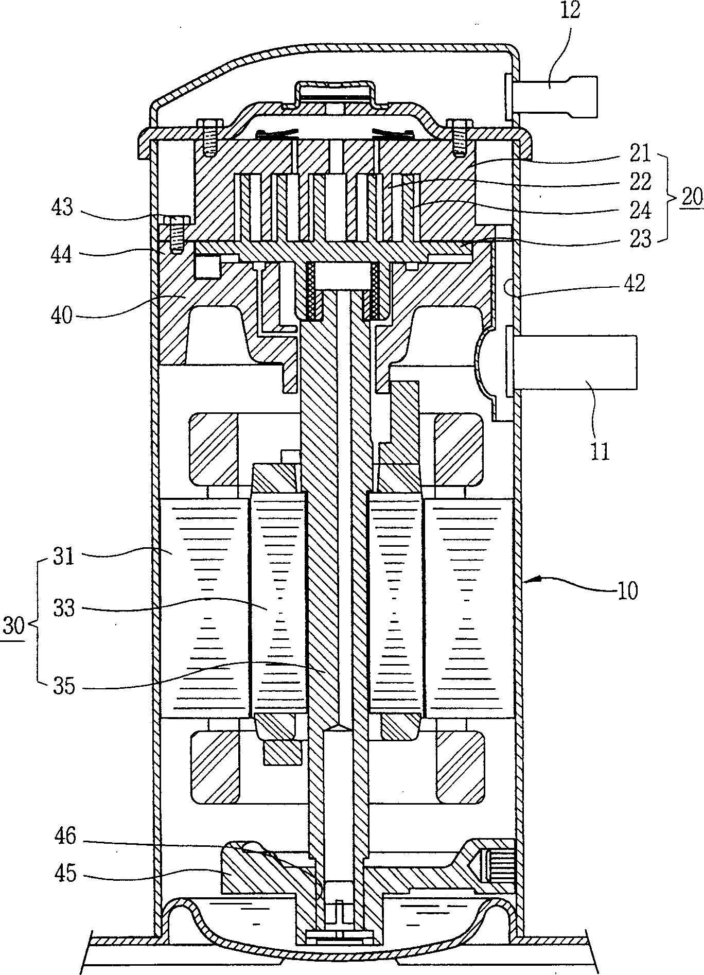
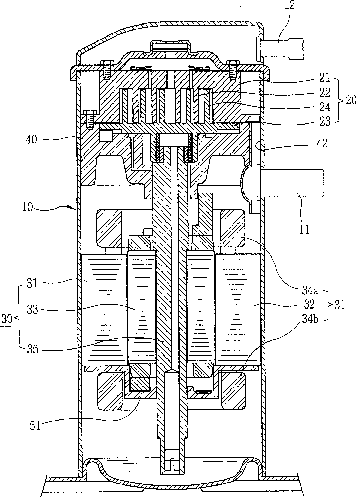
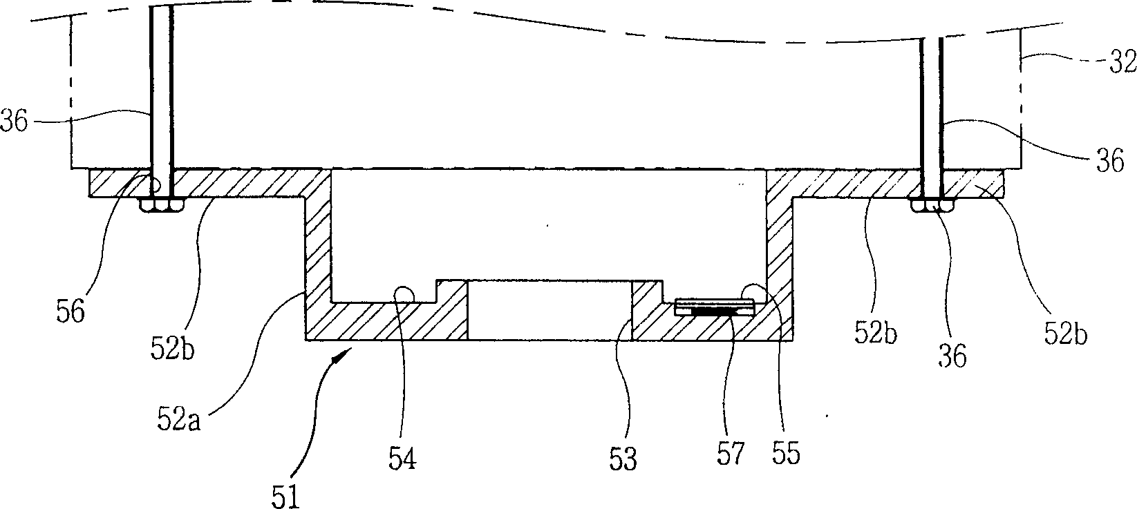
[0026] Below in conjunction with accompanying drawing and specific embodiment the present invention will be described in further detail: figure 2 A longitudinal sectional view showing a scroll compressor according to an embodiment of the present invention, image 3 show figure 2 An enlarged cross-sectional view of the middle and lower brackets, Figure 4 show image 3 Enlarged top view of the middle and lower bracket, Figure 5 show Figure 4 Enlarged cross-sectional view of the middle V-V section.

[0027] As shown in the above drawings, the scroll compressor has the following structure: the inside of the casing 10 is a closed space; the compression unit 20 is installed above the inside of the casing 10 to compress the refrigerant sucked from the outside; the motor 30 is installed in the compressor Below the part 20, the motor shaft is the rotating shaft 35, which provides driving force to the compression part 20 through the rotating shaft 35; the upper frame 40 is arr...


PUM


Abstract

A vortex-type compressor with detachable lower supporter is disclosed. Its cylindrical lower supporter under stator and rotor has flange jaws on its top. Said flange jaws have screen hole for fixing iron core of stator. The lower part of motor shaft is positioned in the central hole on bottom of lower supporter. A ring recess on the bottom of lower supporter is used to recept a lower balance block of lower end of rotor. Its advantages are low cost and preventing reverse rotation.

Description

technical field [0001] The invention belongs to compressors, in particular to a scroll compressor. Background technique [0002] The present invention relates to the invention of the scroll compressor, figure 1 A longitudinal sectional view of a prior art scroll compressor is shown. As shown in the figure, the scroll compressor has the following structure: the inside of the casing 10 is a closed space; the compression part 20 is above the inside of the casing 10 and compresses the refrigerant sucked from the outside; the motor 30 is arranged on the compression part 20 Below, the compression member 20 is driven. [0003] The suction pipe 11 is located on the side of the casing 10 and can suck in refrigerant from the outside; the exhaust pipe 12 is located above the suction pipe 11 and can discharge the refrigerant compressed by the compression unit 20 . [0004] The compression part 20 includes a fixed scroll 21 and an orbiting scroll 23 . The fixed scroll 21 is fixed abo...

Claims


Application Information

Patent Timeline
Patent Type & Authority Applications(China)
IPC IPC(8): F04C18/02F04C29/00
Inventor 赵镛一
Owner LG ELECTRONICS (TIANJIN) APPLIANCES CO LTD
Why Eureka
Try Eureka