Method, device and security system for authenticating marking

A technology of marking and equipment, applied in the field of security systems for marking and identifying objects, to achieve the effect of a wide range of applications

Inactive Publication Date: 2003-07-09
SICPA HLDG SA
View PDF6 Cites 12 Cited by
  • Summary
  • Abstract
  • Description
  • Claims
  • Application Information

AI Technical Summary

Problems solved by technology

This limitation is a consequence of the mechanical constraints (conveyor belt speed) in the inspection process

Method used


Image

  • Method, device and security system for authenticating marking
  • Method, device and security system for authenticating marking
  • Method, device and security system for authenticating marking

Examples


Embodiment Construction

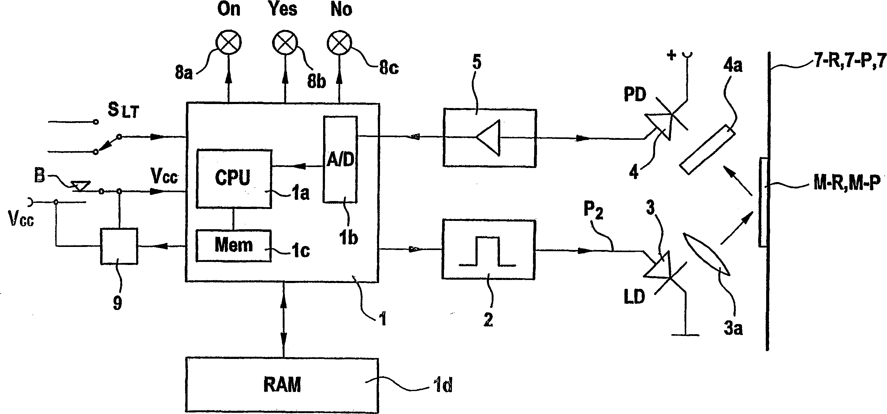
[0052] The security system according to the invention includes microprocessor-based authentication devices such as image 3 shown in the schematic diagram.

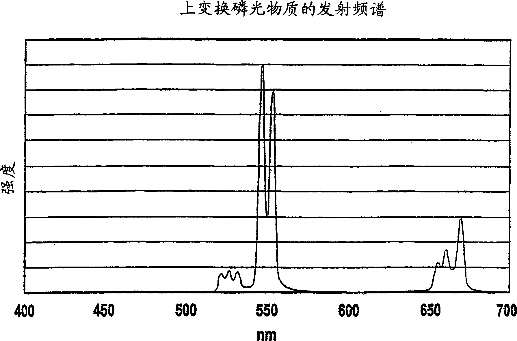
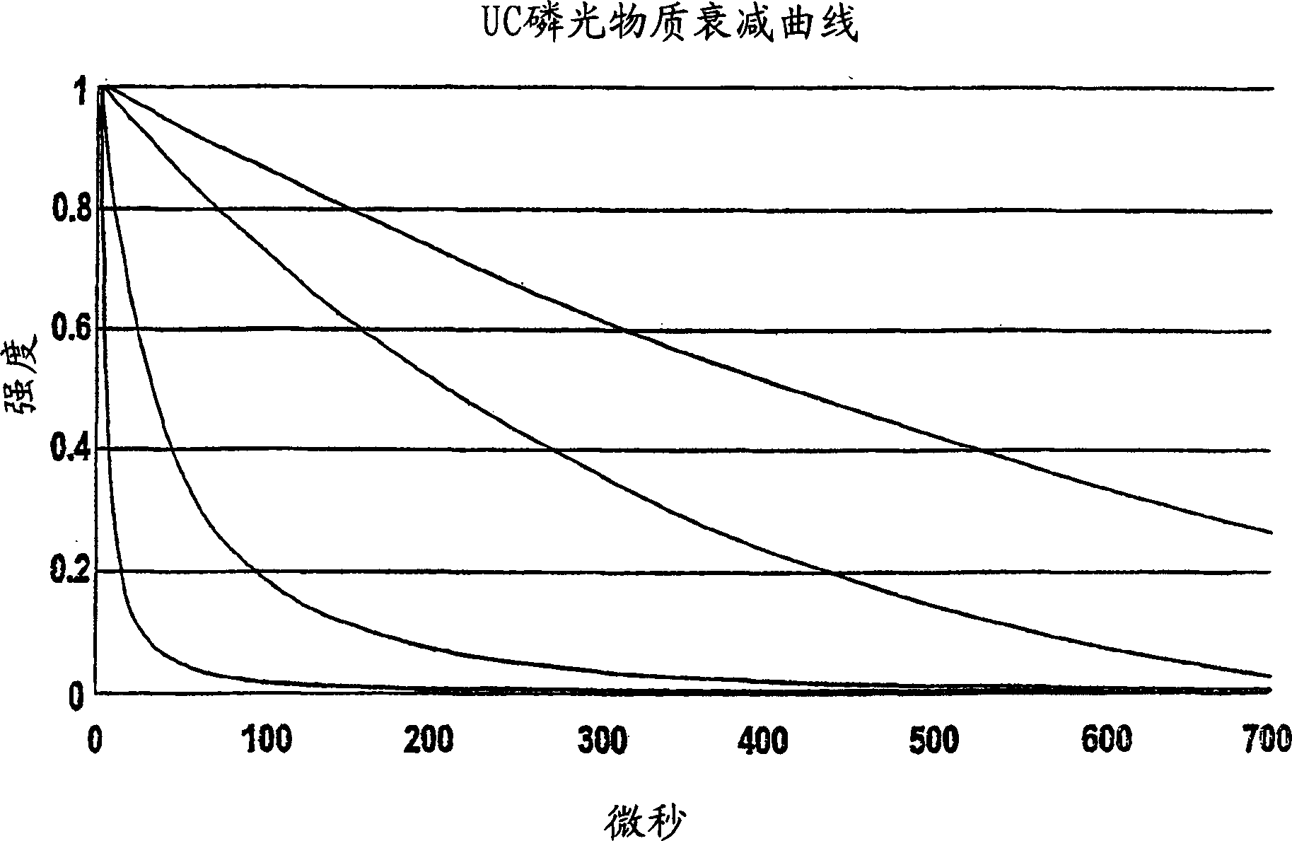
[0053] As representatives of the class of luminescent compounds within the label, 4 Erbium-based up-converting phosphorescent materials with different properties were selected: Gd2O2S: Er, Yb; Y2O2S: Er, Yb; BaY2F8: Er, Yb; NaYF4: Er, Yb. After irradiating with a light source of 950 or 980nm, they all emit green light close to 550nm (such as figure 1 shown). However, for these 4 materials, the lifetime of green phosphorescent emission is quite different, as figure 2 shown.

[0054] Such as image 3 As shown, qualification equipment includes, for example, the AduC812 microconverter utilizing the Analog Devices TM Implemented microcontroller or processor 1. The AduC812 chip includes: 16MHz8052 microprocessor (CPU) 1a with 32 digital I / O lines; 5μs 12-bit analog / digital (A / D) converter 1b; digital / analog converter; in...


PUM


Abstract

The invention refers to a method, device and security system, all for authenticating a marking (M-P), comprising the steps of: exciting said luminescent probe marking (M-P) with at least one excitation pulse (P) of at least one excitation source (3, 31-36), measuring probe intensity values (VP1-VPn) of emission intensity (I) from emission radiation (E) of said luminescent probe marking (M-P) in response to said at least one excitation pulse (P) at time intervals (t1-tn), forming a probe intensity-versus-time emission function of said probe intensity values (VP1-VPn), comparing said probe intensity-versus-time emission function with at least one reference intensity-versus-time emission function, said probe intensity-versus-time emission function and said reference intensity-versus-time emission function are normalized prior to comparison.

Description

field of invention [0001] The present invention belongs to the technical field of security marks made with ink or paint components or bulk materials and documents or products carrying such security marks. The present invention relates to a novel method of exploiting the properties of a certain luminescent pigment contained within said ink, paint composition or product. In particular, the present invention relates to methods and devices for using the afterglow properties of certain luminescent materials and luminescent compounds, and proposes a security system for marking and authenticating objects. Background technique [0002] Luminescent materials are one of the traditional components of security inks or coatings. They convert the energy of excitation radiation of a given wavelength into emitted light of another wavelength. The light emission used may be in the UV range of the electromagnetic spectrum (below 400nm), the visible range (400-700nm) or near the middle of the...

Claims


Application Information

Patent Timeline
Patent Type & Authority Applications(China)
IPC IPC(8): G06K7/10G06K7/12G06K19/14
CPCG06K19/14G07D7/12G07D7/121
Inventor E·米勒P·埃格尔M·塞托
Owner SICPA HLDG SA
Why Eureka
Try Eureka