Current associating and unloading control method for multiple-pump hydraulic system

A hydraulic system and control method technology, applied in fluid pressure actuators, servo motor components, mechanical equipment, etc., can solve the problems of reducing system and component reliability, system reliability and life damage, and large temperature rise of hydraulic systems , to make full use of engine power, reduce energy consumption and temperature rise, and increase energy consumption

Inactive Publication Date: 2003-07-30
陈嘉川
View PDF0 Cites 12 Cited by
  • Summary
  • Abstract
  • Description
  • Claims
  • Application Information

AI Technical Summary

Problems solved by technology

But this method has a lot of shortcomings: First, when the system is not working, the flow of the auxiliary pump must also be combined with the flow of the main pump, which causes unnecessary pressure loss, which not only leads to an increase in energy consumption, but also Increase the temperature rise of the system and reduce the reliability of the system and components; Second, some light-load and low-voltage conditions do not require high operating speeds. At this time, the speed of the actuator can only be controlled by throttling, that is, increased energy consumption, which further increases the temperature rise of the system
[0003] Judging from the current use of wheel loaders in this unloading method, in addition to the increase in energy consumption, the biggest problem is that the temperature rise of the hydraulic system is too large. Some products do not use forced cooling. It can reach 100°C, and it can reach as high as 90°C after forced cooling, which will cause fatal damage to the reliability and life of the system

Method used


Image

  • Current associating and unloading control method for multiple-pump hydraulic system
  • Current associating and unloading control method for multiple-pump hydraulic system
  • Current associating and unloading control method for multiple-pump hydraulic system

Examples


Embodiment Construction

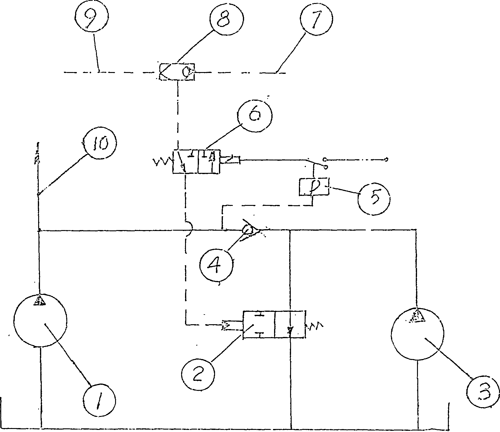
[0015] The present invention will be further described below in conjunction with accompanying drawing.

[0016] figure 1 Among them, the two-position two-way valve 2 is connected in parallel between the main pump 1 and the auxiliary pump 3, the one-way valve 4 is connected in series between the main pump 1 and the two-position two-way valve 2, and the control oil circuit of the two-position two-way valve 2 The electromagnetic reversing valve 6 is connected in series, and the electromagnetic reversing valve is controlled by the control switch 5 . The control switch is normally open, and the confluence control pressure makes the main pump and auxiliary pump confluence. When the load pressure of the main pump reaches the set unloading pressure of the auxiliary pump, the control switch is closed by the signal of the pressure sensor (after amplification), the electromagnetic reversing valve is disconnected, and the control oil circuit of the two-position two-way valve 2 is cut off...


PUM


Abstract

The present invention relates to current association and unloading control method for multiple-pump hydraulic system, especially for loading machine and other heavy mechanical apparatus. The present invention uses hydraulically controlled change valve as current associating and unloading control element for multiple-pump hydraulic system, unlike available systems, which has unloading valve. Thus,the current associating and shutting of the pumps may be controlled at will to lower the power consumption and heat producing amount, raise the reliability of element and system and lower cost.

Description

technical field [0001] The invention relates to a confluence and unloading control method of a multi-pump hydraulic system, in particular to a confluence and unloading control method of a loader hydraulic system. Background technique [0002] At present, the unloading of the auxiliary pump of the hydraulic system used by domestic loaders is controlled by the unloading valve. That is, a one-way valve is connected between the main pump (working pump) and the auxiliary pump (steering pump), so that the hydraulic oil can only pass from the auxiliary pump to the main pump, and vice versa. Then an unloading valve is incorporated between the one-way valve and the auxiliary pump, and the unloading valve is controlled by the load pressure of the main pump. When the load pressure of the main pump is lower than the control pressure of the unloading valve, the auxiliary pumps all participate in the confluence; when the load pressure of the main pump is higher than the control pressure ...

Claims


Application Information

Patent Timeline
Patent Type & Authority Applications(China)
IPC IPC(8): F15B13/02
Inventor 陈嘉川
Owner 陈嘉川
Why Eureka
Try Eureka