Fast DC motor braking method, fast braking motor and brake system

A technology of DC motor and braking system, applied in the direction of reduction device of DC motor, electric motor/converter plug, etc., can solve the problems of easy wear and slip of mechanical device, complex structure, and inability of DC motor to brake quickly.

Inactive Publication Date: 2003-07-30
姚湘江
View PDF0 Cites 10 Cited by
  • Summary
  • Abstract
  • Description
  • Claims
  • Application Information

AI Technical Summary

Problems solved by technology

[0002] None of the existing DC motors can brake quickly. When the power is cut off, the DC motor will still rotate under the action of inertia
At present, the mechanical device braking method is generally used to quickly brake the DC motor, that is, the mechanical device is used to lock the shaft or driven parts. The structure is complex, the braking effect is poor, and the mechanical device is easy to wear, slip, damage and malfunction, which can easily cause a lot of inconvenience. even in distress

Method used


Image

  • Fast DC motor braking method, fast braking motor and brake system
  • Fast DC motor braking method, fast braking motor and brake system
  • Fast DC motor braking method, fast braking motor and brake system

Examples


Embodiment Construction

[0013] Describe in detail below in conjunction with embodiment and accompanying drawing thereof:

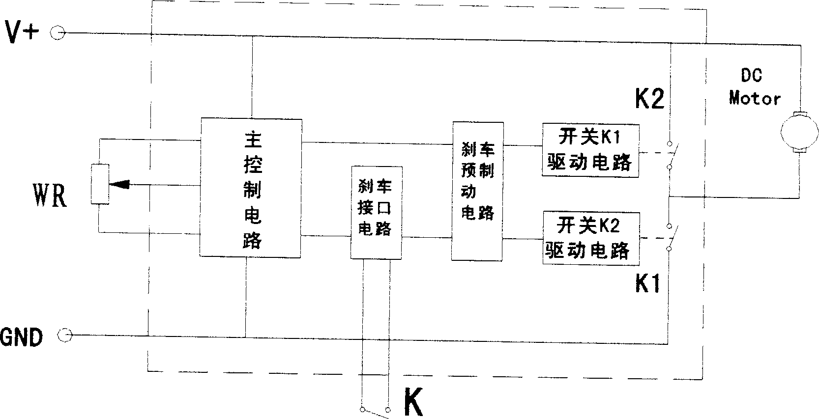
[0014] figure 1 It is a principle block diagram of an electronic electromagnetic driver circuit designed by the method of the invention and used for the brake system of an electric vehicle adopting a single-phase output DC motor. When braking is required, press the brake switch K, the brake pre-brake circuit sends a brake signal, the switch K1 drive circuit works, K1 is opened, and the DC motor is powered off, and then the switch K2 drive circuit works, making K2 close, and the DC motor Short circuit to achieve the purpose of braking.

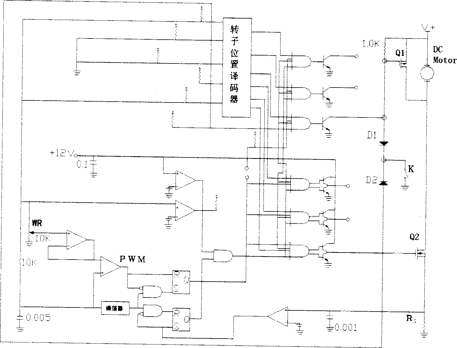
[0015] figure 2 yes figure 1 A circuit diagram of . Among them, the FET Q1 is quite figure 1 The switch K2 in the switch can be used as a freewheeling tube when Q1 is turned off; Q2 is equivalent to figure 1 When the switch K1 is not braking, Q2 is used as the driving power tube of the DC motor. Diodes D1 and D2 here are used as brake pres...


PUM


Abstract

In the present invention, the power of DC motor is cut off in order to create a rotary magnetic field in opposite directio to intertial rotary direction by the current being produced by DC motor intertia in the motor so that very strong magnetic damping will be created at interior of the motor to brake DC motor rapidly. It can decrease the wear of mechanical brake parts.

Description

technical field [0001] The invention relates to a fast braking method of a DC motor, a DC motor capable of fast braking, and an electric vehicle braking system. Background technique [0002] None of the existing DC motors can brake quickly. When the power supply is cut off, the DC motor will still rotate under the effect of inertia. At present, the mechanical device braking method is generally used to quickly brake the DC motor, that is, the mechanical device is used to lock the shaft or driven parts. The structure is complex, the braking effect is poor, and the mechanical device is easy to wear, slip, damage and malfunction, which can easily cause a lot of inconvenience. even distress. Contents of the invention [0003] In view of the above problems, the purpose of the present invention is to provide a DC motor fast braking method that can quickly stop the DC motor after the power is cut off, and a braking system that can quickly brake the DC motor and the electric vehic...

Claims


Application Information

Patent Timeline
Patent Type & Authority Applications(China)
IPC IPC(8): H02P3/12
Inventor 姚湘江
Owner 姚湘江
Why Eureka
Try Eureka