
Projector

A projector and projection lens technology, applied in the field of projectors, can solve the problems that hinder the light weight of the projector, the weight of the lens barrel, and electromagnetic interference, so as to prevent confusion and misoperation, improve storage efficiency, and avoid confusion and misoperation Effect

Inactive Publication Date: 2003-08-06
SEIKO EPSON CORP
View PDF1 Cites 3 Cited by
  • Summary
  • Abstract
  • Description
  • Claims
  • Application Information

AI Technical Summary

Problems solved by technology

[0012] Therefore, there is a problem of causing electromagnetic interference to electronic components inside the projector or other electronic devices outside the projector due to the secondary radiation of electromagnetic waves caused by the lens barrel.
[0013] In addition, if the lens barrel of the projection lens is made of metal as described above, the weight of the lens barrel itself is large, which hinders the problem of reducing the weight of the projector.

Method used


Image

  • Projector
  • Projector
  • Projector

Examples


Embodiment Construction

[0048] specific implementation plan

[0049] Hereinafter, embodiments of the present invention will be described with reference to the drawings.

[0050] 1. The main components of the projector

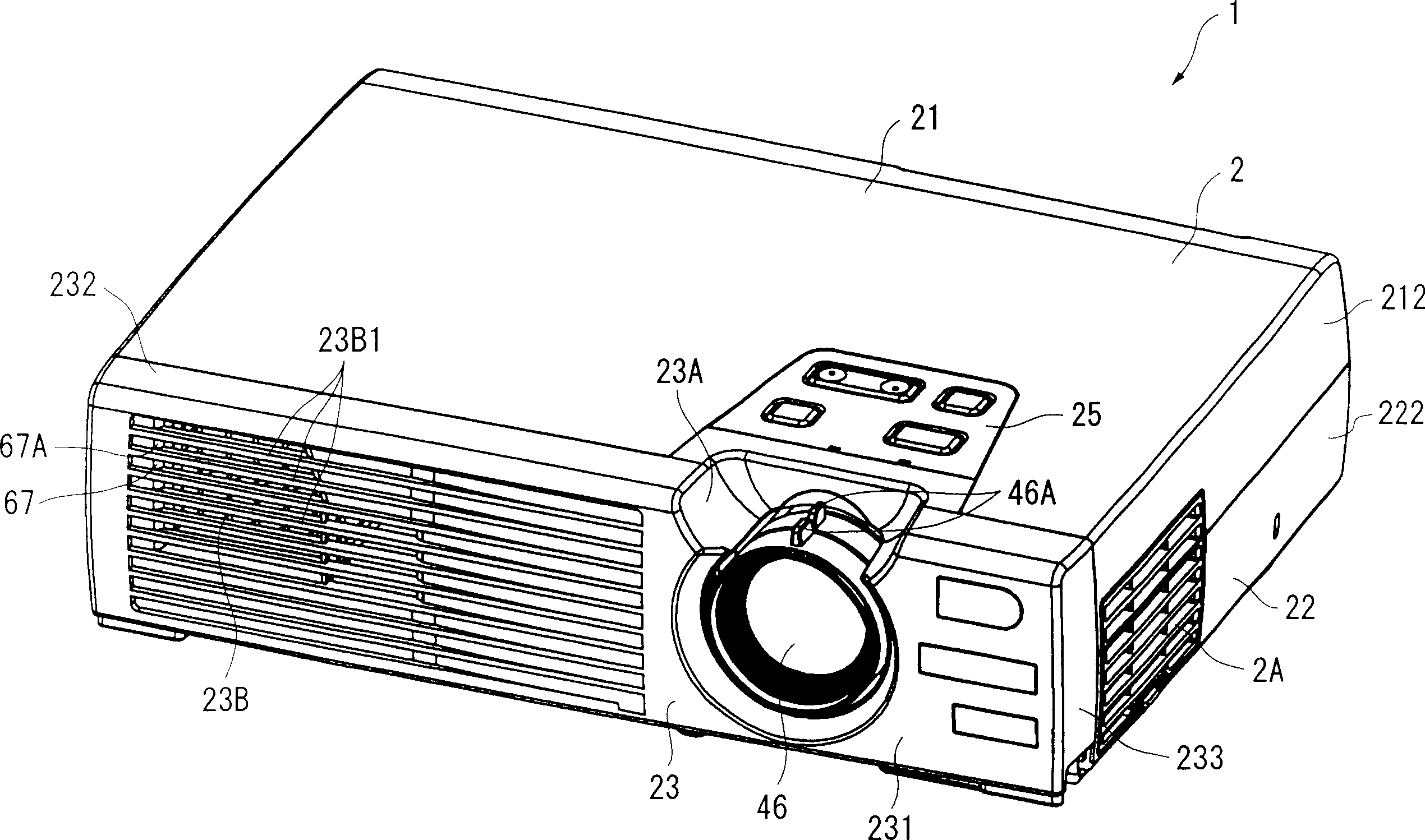
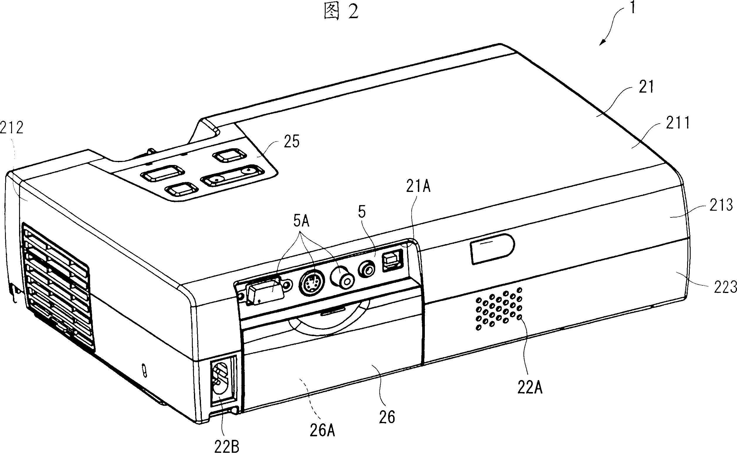
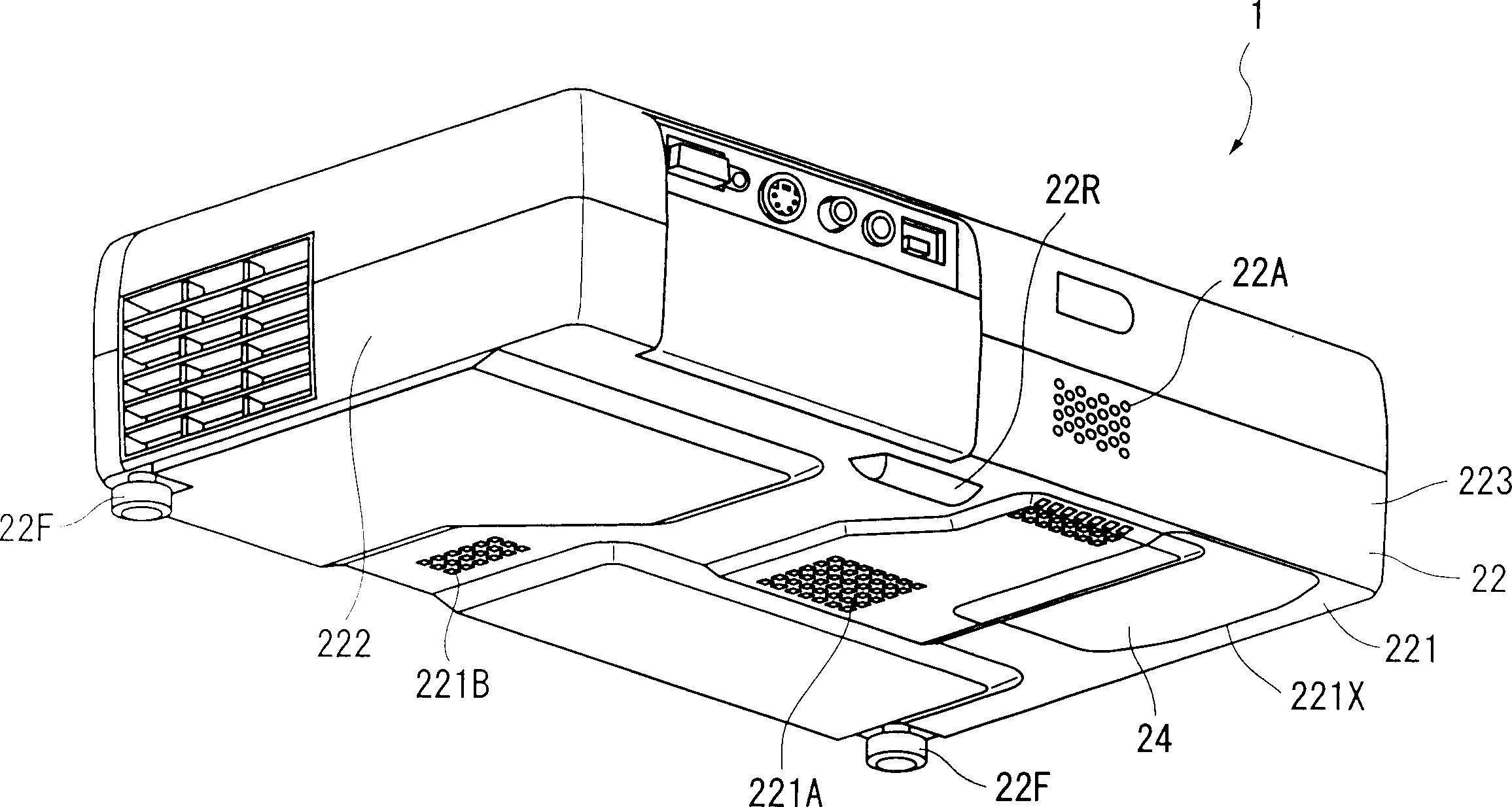
[0051] figure 1 It is a perspective view of the projector 1 of the present invention seen from above. FIG. 2 is a perspective view of the projector 1 viewed from the rear. image 3 It is a perspective view of the projector 1 viewed from below.

[0052] exist Figure 1 ~ Figure 3 Among them, the projector 1 includes an exterior case 2 having a substantially rectangular parallelepiped shape.

[0053] The exterior case 2 is a housing that accommodates the main body of the projector 1 , and includes an upper case 21 , a lower case 22 , and a front case 23 attached across the front side of these cases 21 , 22 . Each of the cases 21 to 23 is made of synthetic resin.

[0054] As shown in FIG. 2 , the upper case 21 is configured to include an upper surface 211 , a side surface 212 , and ...


PUM


Abstract

A projection lens (46) is located at an end of an optical unit (4) of approximately planarly-viewed L-shape, the projection lens enlarging and projecting a color image combined by a cross dichroic prism of an optical device body and including a linearly-advancing barrel (46B) fixed to a head (49) formed on an optical component casing, a cam barrel (46C) provided with a lever (46A), zoom-magnification converting lenses, focus-adjusting lenses and fixed lens, the linearly-advancing barrel (46B) and the cam barrel (46C) being made of polycarbonate, where a control board is disposed above a projection lens (46) to planarly cover the projection lens (46).

Description

technical field [0001] The present invention relates to a projector for projecting an optical image corresponding to image information, comprising a control board for taking in image information for control, and a projection lens composed of a plurality of condensing elements. Background technique [0002] Conventionally, it is known to use projectors for presentations at conferences, academic conferences, exhibitions, and the like. In such a projector, a light beam emitted from a light source device is modulated by a light modulation device based on image information to form an optical image, and the optical image is enlarged and projected. [0003] Generally, in order to magnify and project the optical image modulated by the light modulation device, a projector is equipped with a projection optical system composed of a lens group for changing the magnification of a zoom lens and a lens group for focus adjustment. Reciprocal position, magnification conversion and focus adj...

Claims


Application Information

Patent Timeline
Patent Type & Authority Applications(China)
IPC IPC(8): G02F1/13G03B21/00G03B21/14H04N5/74H04N9/31
CPCH04N9/3141H04N5/7441H04N9/3102
Inventor 中野宽久西田和弘津田昌秀
Owner SEIKO EPSON CORP
Learn More